Sunday, October 21, 2012

Sound Effects Generator 2

This circuit uses the Holtek HT2884 IC to produce 8 different sound effects. All sound effects are generated internally by the HT2884 IC. Power is a 3 Volt battery, but the IC will work with any voltage between 2.5 and 5 Volts. Switch S1 is the on / off switch.
Sound Effects Generator 2 Circuit Diagram:
Sound Effects-Generator-2-Circuit Diagram
The output at pin 10 is amplified and drives a small 8 ohm loudspeaker. Pressing S3 once will generate all the sounds, one after another. S2 can be used to produce a single sound effect, next depression gives the next sound effect. There are 2 lazer guns, 1 dual tone horn sound, 2 bomb sounds, 2 machine gun sounds and a rifle shot sound. Standby current is about 1 uA at 3 Volt, so battery life is very economical.

The IC may be obtained from Maplin Electronics order code AZ52G
Continue[...]

Solid State Relay - Required Only 50uA Drive Current

This circuit demands a control current that is 100 times smaller than that needed by a typical optically isolated solid state relays. It is ideal for battery-powered systems. Using a combination of a high current TRIAC and a very sensitive low current SCR, the circuit can control about 600 watts of power to load while providing full isolation and transient protection.


Continue[...]

Sunday, October 14, 2012

TV Remote Control Jammer

This circuit confuses the infra-red receiver in a TV. It produces a constant signal that interferes with the signal from a remote control and prevents the TV detecting a channel-change or any other command. This allows you to watch your own program without anyone changing the channel !!    The circuit is adjusted to produce a 38kHz signal. The IR diode is called an Infra-red transmitting Diode or IR emitter diode to distinguish it from a receiving diode, called an IR receiver or IR receiving diode. (A Photo diode is a receiving diode).


Circuit Project: TV REMOTE CONTROL JAMMER Circuit

There are so many IR emitters that we cannot put a generic number on the circuit to represent the type of diode. Some types include: CY85G, LD271, CQY37N (45¢), INF3850, INF3880, INF3940 (30¢). The current through the IR LED is limited to 100mA by the inclusion of the two 1N4148 diodes, as these form a constant-current arrangement when combined with the transistor and 5R6 resistor.
Continue[...]

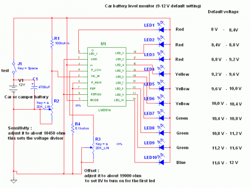
Simple But Reliable Car Battery Tester

This circuit uses the popular and easy to find LM3914 IC. This IC is very simple to drive, needs no voltage regulators (it has a built in voltage regulator) and can be powered from almost every source. This circuit is very easy to explain: When the test button is pressed, the Car battery voltage is feed into a high impedance voltage divider. His purpose is to divide 12V to 1,25V (or lower values to lower values).

This solution is better than letting the internal voltage regulator set the 12V sample voltage to be feed into the internal voltage divider simply because it cannot regulate 12V when the voltage drops lower (linear regulators only step down). Simply wiring with no adjust, the regulator provides stable 1,25V which is fed into the precision internal resistor cascade to generate sample voltages for the internal comparators. Anyway the default setting let you to measure voltages between 8 and 12V but you can measure even from 0V to 12V setting the offset trimmer to 0 (but i think that under 9 volt your car would not start).

Circuit Project: Simple but reliable car battery tester

There is a smoothing capacitor (4700uF 16V) it is used to adsorb EMF noise produced from the ignition coil if you are measuring the battery during the engine working. Diesel engines would not need it, but I'm not sure. If you like more a point graph rather than a bar graph simply disconnect pin 9 on the IC (MODE) from power. The calculations are simple (default)
For the first comparator the voltage is : 0,833 V corresponding to 8 V
* * * * * voltage is : 0,875 V corresponding to 8,4 V
for the last comparator the voltage is : 1,25 V corresponding to 12 V
Have fun, learn and don't let you car battery discharge... ;-)
author: Jonathan Filippi
e-mail: jonathan.filippi@virgilio.it
Continue[...]

Solar-Powered High Efficiency Charger

This is a simple NiCd battery charger powered by solar cells. A solar cell panel or an array of solar cells can charge a battery at more than 80 % efficiency provided the available voltage exceeds the ‘fully charged’ battery voltage by the drop across one diode, which is simply inserted between the solar cell array and the battery. Adding a step-down regulator enables a solar cell array to charge battery packs with various terminal voltages at optimum rates and with efficiencies approaching those of the regulator itself. However, the IC must then operate in an unorthodox fashion (a.k.a. ‘Elektor mode’) regulating the flow of charge current in such a way that the solar array output voltage remains near the level required for peak power transfer. Here, the MAX639 regulates its input voltage instead of its output voltage as is more customary (but less interesting).

Circuit diagram:

Solar-Powered High Efficiency Charger Circuit Diagram

The input voltage is supplied by twelve amorphous solar cells with a minimum surface area of 100 cm2. Returning to the circuit, potential divider R2/R3 disables the internal regulating loop by holding the V-FB (voltage feedback) terminal low, while divider R1/R2+R3 enables LBI (low battery input) to sense a decrease in the solar array output voltage. The resulting deviation from the solar cells’ peak output power causes LBO (low battery output) to pull SHDN (shutdown) low and consequently disable the chip. LBI then senses a rising input voltage, LBO goes high and the pulsating control maintains maximum power transfer to the NiCd cells.

Current limiting inside the MAX639 creates a ‘ceiling’ of 200 mA for I out. Up to five NiCd cells may be connected in series to the charger output. When ‘on’ the regulator chip passes current from pin 6 to pin 5 through an internal switch representing a resistance of less than 1 ohm. Benefiting from the regulator’s low quiescent current (10 microamps typical) and high efficiency (85 %), the circuit can deliver four times more power than the single-diode configuration usually found in simple solar chargers. Coil L1 is a 100-µH suppressor choke rated for 600 mA.
Author: D. Prabakaran - Copyright: Elektor July-August 2004
Continue[...]

Sunday, September 30, 2012

Remote-Controlled Fan Regulator

Using this circuit, you can change the speed of the fan from your couch or bed. Infrared receiver module TSOP1738 is used to receive the infrared signal transmitted by remote control. The circuit is powered by regulated 9V. The AC mains is stepped down by transformer X1 to deliver a secondary output of 12V-0-12V. The transformer output is rectified by full-wave rectifier comprising diodes D1 and D2, filtered by capacitor C9 and regulated by 7809 regulator to provide 9V regulated output. Any button on the remote can be used for controlling the speed of the fan. Pulses from the IR receiver module are applied as a trigger signal to timer NE555 (IC1) via LED1 and resistor R4.
Circuit Diagram :
Remote-Controlled Fan Regulator Circuit Diagram
IC1 is wired as a monostable multivibrator to delay the clock given to decade counter-cum-driver IC CD4017 (IC2).Out of the ten outputs of decade counter IC2 (Q0 through Q9), only five (Q0 through Q4) are used to control the fan. Q5 output is not used, while Q6 output is used to reset the counter. Another NE555 timer (IC3) is also wired as a monostable multivibrator. Combination of one of the resistors R5 through R9 and capacitor C5 controls the pulse width.  The output from IC CD4017 (IC2) is applied to resistors R5 through R9. If Q0 is high capacitor C5 is charged through resistor R5, if Q1 is high capacitor C5 is charged through resistor R6, and so on.
Optocoupler MCT2E (IC5) is wired as a zero-crossing detector that supplies trigger pulses to monostable multivibrator IC3 during zero crossing. Opto-isolator MOC3021 (IC4) drives triac BT136. Resistor R13 (47-ohm) and capacitor C7 (0.01µF) combination is used as snubber network for triac1 (BT136). As the width of the pulse decreases, firing angle of the triac increases and speed of the fan also increases. Thus the speed of the fan increases when we press any button on the remote control. Assemble the circuit on a general-purpose PCB and house it in a small case such that the infrared sensor can easily receive the signal from the remote transmitter.
Continue[...]

Storage Battery Exerciser

A motorcycle or boat battery that is not needed over the winter is usually charged before being put away for the winter, after which it remains standing unused for months on end. As a result, it accumulates deposits of lead sludge, which can result in reduced capacity or even complete failure of the battery. If you don’t keep active, you rust! To avoid this, it’s necessary to keep the battery active even during the winter. This circuit does such a good job of exercising the battery that it doesn’t have to be recharged during the winter. It only has to be fully charged again in the spring before being used again. IC1.A is an astable multivibrator with an asymmetric duty cycle. The output is High for around 0.6 s and Low for around 40 s. IC1.B is wired as a comparator that constantly monitors the battery voltage. Its threshold voltage is set to 11.0 V using the trimpot.

Circuit diagram:
Storage Battery Exerciser Circuit Diagram

As soon as the battery voltage drops below this value, the comparator goes Low and D6 is cut off, allowing the second astable multivibrator IC1.C to oscillate at approximately 1.2 Hz. LED D7 then blinks to indicate that the battery must be charged. As long as the battery voltage is greater than 11 V, IC1.B is High. IC1.A is Low most of the time, and in this state D4 conducts and the inverting input of IC1.D is Low. This means that IC1.D is High most of the time, with T1 cut off. T1 only conducts during the 0.6-s intervals when IC1.A is High. In this state it allows current to pass through the lamp (12 V / 3 W), which forms the actual load for the battery. After this, darkness prevails again for 40 s. The average current consumption is approximately 5 mA. At this rate, a relatively new 40-Ah battery will take around one year to become fully discharged. However, this can vary depending on the condition of the battery, and it may be necessary to ‘top up’ the battery once during the winter.
Author: Ludwig Libertin - Copyright: Elektor Electronics
Continue[...]