Saturday, November 16, 2013
Dual Mode Microphone Pre Amplifier
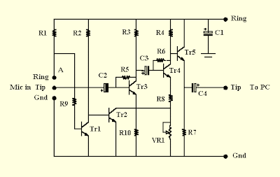
R1 = R7 = 4k7; R2 = R3 = 47k; R4 = 39k; R5 = R6 = 100k; R8 = 220; R9 = 10k; R10 = 2k2 (all 1/8 Watt). VR1 = 10k
horizontal pre-set. C1 = 47uF; C2 = C3 = C4 = 10uF (all 10V or greater, miniature radial electrolytics). Tr1 = Tr2 = Tr3 = Tr4 = Tr5 = BC108, BC184, BC547, ZTX337 or similar low-power (preferably low noise) NPN transistor

Monday, August 27, 2012
Sound Activated Lights

Caution. Since the sound activated lights uses 230V AC, many of its points are at AC mains voltage. It could give you lethal shock if you are not careful. So if you don’t know much about working with line voltages, do not attempt to construct this circuit. We will not be responsible for any kind of resulting loss or damage.
Friday, June 10, 2011
A Low Cost Hearing Aid Circuit
Small and portable unit, Useful for old men and old women
This low-cost, general-purpose electronic hearing aid works off 3V DC (2x1.5V battery). The circuit can be easily assembled on a veroboard. For easy assembling and maintenance, use an 8-pin DIP IC socket for TDA2822M.
Circuit Diagrams:
 A Low Cost hearing Aid Circuit
Parts:
P1 = 10K
R1 = 2.2K
R2 = 330K
R3 = 680R
R4 = 33R
R5 = 100R
R6 = 4.7R
R7 = 4.7R
R8 = 220R
C1 = 0.01uF-10V
C2 = 100nF-63V
C3 = 47uF-10V
C4 = 10uF-10V
C5 = 0.01uF-10V
C6 = 100uF-10V
C7 = 100nF-63V
C8 = 100nF-63V
D1 = Red LED
Q1 = BC547
IC1 = TDA2822M
EP1 = Mono Earphone 32R
SW1 = On-Off Switch
Circuit Operation:
In this circuit, transistor Q1 and associated components form the audio signal preamplifier for the acoustic signals picked up by the condenser microphone and converted into corresponding electrical signals. Resistor R5 and capacitor C3 decouple the power supply of the preamplifier stage. Resistor R1 biases the internal circuit of the low-voltage condenser microphone for proper working. The audio output from the preamplifier stage is fed to the input of the medium-power amplifier circuit via capacitor C2 and volume control P1.
The medium-power amplifier section is wired around popular audio amplifier IC TDA2822M (not TDA2822). This IC, specially designed for portable low-power applications, is readily available in 8-pin mini DIP package. Here the IC is wired in bridge configuration to drive the 32-ohm general-purpose monophonic earphone. Red LED (D1) indicates the power status. Resistor R8 limits the operating current of D1. The audio output of this circuit is 10 to 15mW and the quiescent current drain is below 1 mA.
Source : www.electronsforu.com
Amplified Ear Circuit
Useful to listen in faint sounds, 1.5V Battery operation
This circuit, connected to 32 Ohm impedance mini-earphones, can detect very remote sounds. Useful for theatre, cinema and lecture goers: every word will be clearly heard. You can also listen to your television set at a very low volume, avoiding to bother relatives and neighbors. Even if you have a faultless hearing, you may discover unexpected sounds using this device: a remote bird twittering will seem very close to you.
Circuit Diagram:

Parts :
P1 = 22K
R1 = 10K
R2 = 1M
R3 = 4K7
R4 = 100K
R5 = 3K9
R6 = 1K5
R7 = 100K
R8 = 100R
R9 = 10K
C1 = 100nF 63V
C2 = 100nF 63V
C3 = 1µF 63V
C4 = 10µF 25V
C5 = 470µF 25V
C6 = 1µF 63V
D1 = 1N4148
Q1 = BC547
Q2 = BC547
Q3 = BC547
Q4 = BC337
J1 = Stereo 3mm. Jack socket
B1 = 1.5V Battery (AA or AAA cell etc.)
SW1 = SPST Switch (Ganged with P1)
MIC1 = Miniature electret microphone
Circuit Operation :
The heart of the circuit is a constant-volume control amplifier. All the signals picked-up by the microphone are amplified at a constant level of about 1 Volt peak to peak. In this manner very low amplitude audio signals are highly amplified and high amplitude ones are limited. This operation is accomplished by Q3, modifying the bias of Q1 (hence its AC gain) by means of R2.
A noteworthy feature of this circuit is 1.5V battery operation. Typical current drawing: 7.5mA.
Notes:
- Due to the constant-volume control, some users may consider P1 volume control unnecessary. In most cases it can be omitted, connecting C6 to C3. In this case use a SPST slider or toggle switch as SW1.
- Please note the stereo output Jack socket (J1) connections: only the two inner connections are used, leaving open the external one. In this way the two earpieces are wired in series, allowing mono operation and optimum load impedance to Q4 (64 Ohm).
- Using suitable miniature components, this circuit can be enclosed in a very small box, provided by a clip and hanged on one's clothes or slipped into a pocket.
- Gary Pechon from Canada reported that the Amplified Ear is so sensitive that he can hear a whisper 7 meters across the room.
- He hooked a small relay coil to the input and was able to locate power lines in his wall. He was also able to hear the neighbor's stereo perfectly: he could pick up the signals sent to the speaker voice coil through a plaster wall.
- Gary suggests that this circuit could make also a good electronic stethoscope.
Source : www.redcircuits.com