Showing posts with label TIMER. Show all posts
Showing posts with label TIMER. Show all posts
Wednesday, January 22, 2014
Digital Clock with Timer and Solar Panel Regulator
This is a combination digital clock timer and solar panel charge controller used to maintain a deep cycle battery from a solar panel. The timer output is used to control a 12 volt load for a 32 minute time interval each day. Start time is set using 9 dip switches and ends 32 minutes later. The 32 minute duration is set by selecting the 5th bit (2^5 = 32) of a 4040 binary counter (pin 2). The timer also has a manual toggle switch so the load can be manually switched on or off and automatically shuts off after 32 minutes. The time duration can be longer or shorter (8,16,32,64,128,256 minutes etc.) by selecting the appropriate bit of the counter. The timer circuit is shown in the lower schematic just above the regulator.
The basic clock circuit (top schematic below) is similar to the binary clock (on another page) and uses 7 ICs to produce the 20 digital bits for 12 hour time, plus AM and PM. A standard watch crystal oscillator (32,768) is used as the time base and is divided down to 1/2 half second by the 4020 binary counter. One half of a 4013 data latch is used to divide the 1/2 second signal by 2 and produce a one second pulse that drives the seconds counter (74HC390 colored purple). The minutes are advanced by decoding 60 seconds (40 + 20) and then resetting the seconds counter to 0 and at the same time advancing the minutes counter. The same procedure is used to advance the hours. The second half of the 4013 latch is used to indicate AM or PM and is toggled by decoding 13 hours and resetting the hours to 0 and then advancing the hours to "one".
The clock display circuit is shown in the second drawing below and uses 6 more ICs to decode the binary data and drive four seven segment LED displays. The 10s of hours digit is driven with a single 3904 transistor. Two multiplexer circuits (4053) are used to manually select either minutes or seconds for the right two display digits. The two switches shown between the 4053s and below the left 4053 are both part of one DPDT switch which selects either seconds or minutes for the 1X and 10X digits. This switch is shown in the seconds position and the hours digits are blanked with a low signal on pin 4 of the 4511.
The display can also be toggled on and off (totally blank) using a set/reset latch made from a couple 74HC00 NAND gates. A momentary DPDT switch is used to control the latch and toggle the display on or off. The second pole of this switch is used on the upper drawing (connected to the run/stop switch) to set the hours and minutes. Thus this same switch performs both functions of blanking the display and setting the time. The run/stop switch is shown in the normal running mode and supplies a low signal to a NAND gate which prevents accidental setting the time while the clock is running.
The run/stop switch also turns on the display (through the diode D2) when in the stop position. The procedure for setting the clock would be to set the (run/stop) switch the stop position and the (seconds/minutes) switch to the minutes position. Then toggle the momentary switch to set minutes and hours of the current time plus one minute. The clock can then be started with the run/stop switch at precisely the right time (+/- 0.5 seconds).
The voltage regulator in the lower drawing maintains the battery at 13.6 volts and also supplies the clock and timer circuits with 4.3 volts. The charge LED indicator only comes on when the regulator is supplying max charge to the battery. When the battery voltage reaches 13.6 the regulator reduces the current to whatever is necessary to maintain the voltage and the charge indicator will turn off. The unit I built also included a battery condition indicator (voltmeter using 4 LEDs) to indicate the battery condition so that a failure of the regulator would be indicated by the charge indicator LED turned off and less than 4 LEDs lit on the voltmeter.
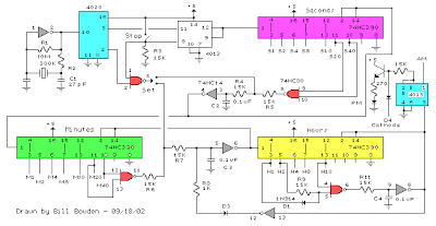 |
| Basic Clock Circuit Diagram |
The basic clock circuit (top schematic below) is similar to the binary clock (on another page) and uses 7 ICs to produce the 20 digital bits for 12 hour time, plus AM and PM. A standard watch crystal oscillator (32,768) is used as the time base and is divided down to 1/2 half second by the 4020 binary counter. One half of a 4013 data latch is used to divide the 1/2 second signal by 2 and produce a one second pulse that drives the seconds counter (74HC390 colored purple). The minutes are advanced by decoding 60 seconds (40 + 20) and then resetting the seconds counter to 0 and at the same time advancing the minutes counter. The same procedure is used to advance the hours. The second half of the 4013 latch is used to indicate AM or PM and is toggled by decoding 13 hours and resetting the hours to 0 and then advancing the hours to "one".
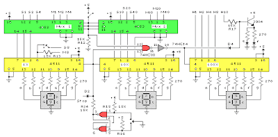 |
| Clock Display Circuit Diagram |
The clock display circuit is shown in the second drawing below and uses 6 more ICs to decode the binary data and drive four seven segment LED displays. The 10s of hours digit is driven with a single 3904 transistor. Two multiplexer circuits (4053) are used to manually select either minutes or seconds for the right two display digits. The two switches shown between the 4053s and below the left 4053 are both part of one DPDT switch which selects either seconds or minutes for the 1X and 10X digits. This switch is shown in the seconds position and the hours digits are blanked with a low signal on pin 4 of the 4511.
The display can also be toggled on and off (totally blank) using a set/reset latch made from a couple 74HC00 NAND gates. A momentary DPDT switch is used to control the latch and toggle the display on or off. The second pole of this switch is used on the upper drawing (connected to the run/stop switch) to set the hours and minutes. Thus this same switch performs both functions of blanking the display and setting the time. The run/stop switch is shown in the normal running mode and supplies a low signal to a NAND gate which prevents accidental setting the time while the clock is running.
 |
| Clock Timer Circuit Diagram |
The run/stop switch also turns on the display (through the diode D2) when in the stop position. The procedure for setting the clock would be to set the (run/stop) switch the stop position and the (seconds/minutes) switch to the minutes position. Then toggle the momentary switch to set minutes and hours of the current time plus one minute. The clock can then be started with the run/stop switch at precisely the right time (+/- 0.5 seconds).
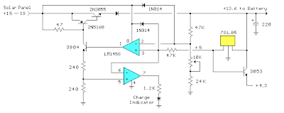 |
| Voltage Regulator (13.6 volts) |
The voltage regulator in the lower drawing maintains the battery at 13.6 volts and also supplies the clock and timer circuits with 4.3 volts. The charge LED indicator only comes on when the regulator is supplying max charge to the battery. When the battery voltage reaches 13.6 the regulator reduces the current to whatever is necessary to maintain the voltage and the charge indicator will turn off. The unit I built also included a battery condition indicator (voltmeter using 4 LEDs) to indicate the battery condition so that a failure of the regulator would be indicated by the charge indicator LED turned off and less than 4 LEDs lit on the voltmeter.

Friday, November 29, 2013
NE555 IC Timer
The 555 Timer is an integrated circuit (chip) implementing a variety of timer and multivibrator applications. The IC was designed and invented by Hans R. Camenzind. It was designed in 1970 and introduced in 1971 by Signetics (later acquired by Philips). The original name was the SE555/NE555 and was called "The IC Time Machine".
 The 555 gets its name from the three 5-k Ohm resistors used in typical early implementations. It is still in wide use, thanks to its ease of use, low price and good stability. As of 2003[update], 1 billion units are manufactured every year.
The 555 timer is one of the most popular and versatile integrated circuits ever produced. It includes 23 transistors, 2 diodes and 16 resistors on a silicon chip installed in an 8-pin mini dual-in-line package (DIP-8).
The 555 has three operating modes:
* Monostable mode: in this mode, the 555 functions as a "one-shot". Applications include timers, missing pulse detection, bouncefree switches, touch switches, Frequency Divider,Capacitance Measurement, Pulse Width Modulation (PWM) etc
* Astable - Free Running mode: the 555 can operate as an oscillator. Uses include LED and lamp flashers, pulse generation, logic clocks, tone generation, security alarms, pulse position modulation, etc.
* Bistable mode or Schmitt trigger: the 555 can operate as a flip-flop, if the DIS pin is not connected and no capacitor is used. Uses include bouncefree latched switches, etc.
The connection of the pins is as follows:

Nr. Name Purpose
1 GND Ground, low level (0V)
2 TR A short pulse high → low on the trigger starts the timer
3 Q During a timing interval, the output stays at +VCC
4 R A timing interval can be interrupted by applying a reset pulse to low (0V)
5 CV Control voltage allows access to the internal voltage divider (2/3 VCC)
6 THR The threshold at which the interval ends (it ends if U.thr → 2/3 VCC)
7 DIS Connected to a capacitor whose discharge time will influence the timing interval
8 V+, VCC The positive supply voltage which must be between 3 and 15 V
In the astable mode, the high time from each pulse is given by
high = 0.693.(R1 + R2).C
and the low time from each pulse is given by
low = 0.693.R2.C
where R1 and R2 are the values of the resistors in ohms and C is the value of the capacitor in farads.
Specs
These specifications apply to the NE555. Other 555 timers can have better specifications depending on the grade (military, medical, etc).
* Supply voltage (VCC) 4.5 to 15 V
* Supply current (VCC = +5 V) 3 to 6 mA
* Supply current (VCC = +15 V) 10 to 15 mA
* Output current (maximum) 200 mA
* Power dissipation 600 mW
* Operating temperature 0 to 70 °C
Thursday, September 22, 2011
BURGLAR ALARM USING IC TIMER 555/556 ELECTRONIC DIAGRAM

BURGLAR ALARM USING IC TIMER 555/556 ELECTRONIC DIAGRAM
circuit diagram of burglar alarm using IC timer 555/556 is functioned as an alarm to prevent thief entering your house. The alarm would produce loud sound when a thin wire connecting resistor R1 with IC pin no 4 is broken. Thin fiber is used as the wire. The thinner the wire, the more responsive the alarm. This circuit needs 5-15V power supply, buzzer is used as a speaker. Here is the circuit schematic :
Parts list :
- Resistor R1 : 10k
- Resistor R2 : 68k
- Resistor R3 : 1k
- Polar capacitor C1 : 1uF/15 B
- Capacitor C2-C3 : 0.01uF
- IC Timer : NE555
Subscribe to:
Posts (Atom)