Showing posts with label REGULATOR. Show all posts
Showing posts with label REGULATOR. Show all posts
Wednesday, January 22, 2014
Digital Clock with Timer and Solar Panel Regulator
This is a combination digital clock timer and solar panel charge controller used to maintain a deep cycle battery from a solar panel. The timer output is used to control a 12 volt load for a 32 minute time interval each day. Start time is set using 9 dip switches and ends 32 minutes later. The 32 minute duration is set by selecting the 5th bit (2^5 = 32) of a 4040 binary counter (pin 2). The timer also has a manual toggle switch so the load can be manually switched on or off and automatically shuts off after 32 minutes. The time duration can be longer or shorter (8,16,32,64,128,256 minutes etc.) by selecting the appropriate bit of the counter. The timer circuit is shown in the lower schematic just above the regulator.
The basic clock circuit (top schematic below) is similar to the binary clock (on another page) and uses 7 ICs to produce the 20 digital bits for 12 hour time, plus AM and PM. A standard watch crystal oscillator (32,768) is used as the time base and is divided down to 1/2 half second by the 4020 binary counter. One half of a 4013 data latch is used to divide the 1/2 second signal by 2 and produce a one second pulse that drives the seconds counter (74HC390 colored purple). The minutes are advanced by decoding 60 seconds (40 + 20) and then resetting the seconds counter to 0 and at the same time advancing the minutes counter. The same procedure is used to advance the hours. The second half of the 4013 latch is used to indicate AM or PM and is toggled by decoding 13 hours and resetting the hours to 0 and then advancing the hours to "one".
The clock display circuit is shown in the second drawing below and uses 6 more ICs to decode the binary data and drive four seven segment LED displays. The 10s of hours digit is driven with a single 3904 transistor. Two multiplexer circuits (4053) are used to manually select either minutes or seconds for the right two display digits. The two switches shown between the 4053s and below the left 4053 are both part of one DPDT switch which selects either seconds or minutes for the 1X and 10X digits. This switch is shown in the seconds position and the hours digits are blanked with a low signal on pin 4 of the 4511.
The display can also be toggled on and off (totally blank) using a set/reset latch made from a couple 74HC00 NAND gates. A momentary DPDT switch is used to control the latch and toggle the display on or off. The second pole of this switch is used on the upper drawing (connected to the run/stop switch) to set the hours and minutes. Thus this same switch performs both functions of blanking the display and setting the time. The run/stop switch is shown in the normal running mode and supplies a low signal to a NAND gate which prevents accidental setting the time while the clock is running.
The run/stop switch also turns on the display (through the diode D2) when in the stop position. The procedure for setting the clock would be to set the (run/stop) switch the stop position and the (seconds/minutes) switch to the minutes position. Then toggle the momentary switch to set minutes and hours of the current time plus one minute. The clock can then be started with the run/stop switch at precisely the right time (+/- 0.5 seconds).
The voltage regulator in the lower drawing maintains the battery at 13.6 volts and also supplies the clock and timer circuits with 4.3 volts. The charge LED indicator only comes on when the regulator is supplying max charge to the battery. When the battery voltage reaches 13.6 the regulator reduces the current to whatever is necessary to maintain the voltage and the charge indicator will turn off. The unit I built also included a battery condition indicator (voltmeter using 4 LEDs) to indicate the battery condition so that a failure of the regulator would be indicated by the charge indicator LED turned off and less than 4 LEDs lit on the voltmeter.
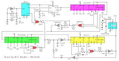 |
| Basic Clock Circuit Diagram |
The basic clock circuit (top schematic below) is similar to the binary clock (on another page) and uses 7 ICs to produce the 20 digital bits for 12 hour time, plus AM and PM. A standard watch crystal oscillator (32,768) is used as the time base and is divided down to 1/2 half second by the 4020 binary counter. One half of a 4013 data latch is used to divide the 1/2 second signal by 2 and produce a one second pulse that drives the seconds counter (74HC390 colored purple). The minutes are advanced by decoding 60 seconds (40 + 20) and then resetting the seconds counter to 0 and at the same time advancing the minutes counter. The same procedure is used to advance the hours. The second half of the 4013 latch is used to indicate AM or PM and is toggled by decoding 13 hours and resetting the hours to 0 and then advancing the hours to "one".
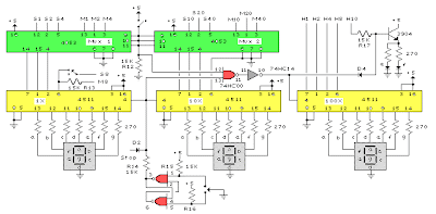 |
| Clock Display Circuit Diagram |
The clock display circuit is shown in the second drawing below and uses 6 more ICs to decode the binary data and drive four seven segment LED displays. The 10s of hours digit is driven with a single 3904 transistor. Two multiplexer circuits (4053) are used to manually select either minutes or seconds for the right two display digits. The two switches shown between the 4053s and below the left 4053 are both part of one DPDT switch which selects either seconds or minutes for the 1X and 10X digits. This switch is shown in the seconds position and the hours digits are blanked with a low signal on pin 4 of the 4511.
The display can also be toggled on and off (totally blank) using a set/reset latch made from a couple 74HC00 NAND gates. A momentary DPDT switch is used to control the latch and toggle the display on or off. The second pole of this switch is used on the upper drawing (connected to the run/stop switch) to set the hours and minutes. Thus this same switch performs both functions of blanking the display and setting the time. The run/stop switch is shown in the normal running mode and supplies a low signal to a NAND gate which prevents accidental setting the time while the clock is running.
 |
| Clock Timer Circuit Diagram |
The run/stop switch also turns on the display (through the diode D2) when in the stop position. The procedure for setting the clock would be to set the (run/stop) switch the stop position and the (seconds/minutes) switch to the minutes position. Then toggle the momentary switch to set minutes and hours of the current time plus one minute. The clock can then be started with the run/stop switch at precisely the right time (+/- 0.5 seconds).
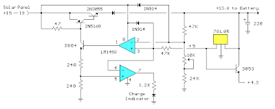 |
| Voltage Regulator (13.6 volts) |
The voltage regulator in the lower drawing maintains the battery at 13.6 volts and also supplies the clock and timer circuits with 4.3 volts. The charge LED indicator only comes on when the regulator is supplying max charge to the battery. When the battery voltage reaches 13.6 the regulator reduces the current to whatever is necessary to maintain the voltage and the charge indicator will turn off. The unit I built also included a battery condition indicator (voltmeter using 4 LEDs) to indicate the battery condition so that a failure of the regulator would be indicated by the charge indicator LED turned off and less than 4 LEDs lit on the voltmeter.

Thursday, October 27, 2011
SOFT START MECHANISM FOR L200 VOLTAGE REGULATOR ELECTRONIC DIAGRAM

SOFT START MECHANISM FOR L200 VOLTAGE REGULATOR ELECTRONIC DIAGRAM
Ic (constant current) is charge capacitor C, where Ic = Vsc/R.
The output reaches its nominal value after the time ton. Vo-Vsc=(Ic.ton)/C.
ton=C.[(Vo-0.45)/0.45].R = CVoR/0.45.
Vo follows the voltage in pin 2 at less than 0.45 volt. It is because voltage of more than 0.45 V can’t be produced between pin 2 and pin 5.
Wednesday, October 26, 2011
VOLTAGE REGULATOR MODULES (VRM) A SOLUTION FOR CPU CORE VOLTAGE ELECTRONIC CIRCUIT

VOLTAGE REGULATOR MODULES (VRM) A SOLUTION FOR CPU CORE VOLTAGE ELECTRONIC CIRCUIT
For each phase, the components on point (2) above which constitute all the power components are placed on a small plug-in board of 1.15? x 0.85? that delivers 40 Amps and receives the PWM TTL signal from the controller. This module has a footprint of about 0.85? x 0.25? of the motherboard space and may be placed anywhere on the board as close as possible to theCPU reducing the transmission impedance and losses and giving the Motherboard designer the flexibility to optimize the power and PCB space utilization. Each modular board may be fitted individually with its own heat sink.
Wednesday, September 28, 2011
L200 VOLTAGE REGULATOR SOFT START MECHANISM ELECTRONIC DIAGRAM

L200 VOLTAGE REGULATOR SOFT START MECHANISM ELECTRONIC DIAGRAM
The Vo follows the voltage at pin 2 at less than 0.45 V since a voltage of more than 0.45 V cannot be produced between pins 5 and pins 2.
Constant current ic is charge capacitor C, where
ic= Vsc/R
After the time ton, the output reaches it’s nominal value
Vo-Vsc = (Ic.ton)/C
ton=C.[(Vo-0.45)/0.45].R = CVoR/0.45
Friday, September 23, 2011
ADJUSTABLE 1.5A STEP DOWN 1.5MHz SWITCHING REGULATOR ELECTRONIC DIAGRAM

ADJUSTABLE 1.5A STEP DOWN 1.5MHz SWITCHING REGULATOR ELECTRONIC DIAGRAM
However, an Adjustable 1.5A Step Down 1.5 MHz switching regulator circuit can also be used to overcome such problem. It uses ST1S03 step down DC-DC converter. The ST1S03 can also be used to power low-voltage digital core in HDD application .
With input voltage range 3V to 16V, the ST1S03 can gives current up to 1.5A. The circuit can use tiny surface-mount components due to an high switching frequency (1.5 MHz). Resistor divider is used to set the output voltage value. Components needed to build the divided are capacitors (2 pieces), schottky diode (1 piece), and inductor (1 piece).
Thursday, September 22, 2011
PRECISION POWER REGULATOR ELECTRONIC DIAGRAM

PRECISION POWER REGULATOR ELECTRONIC DIAGRAM
A precision voltage source is quite easy, except when the voltage should be consistent over wide range of ambient temperature. This requirement might be needed in high precision measurement system environment. For example, to provide reference voltage in analog to digital conversion.
3V DC to 5V DC REGULATED POWER SUPPLY ELECTRONIC DIAGRAM

3V DC to 5V DC REGULATED POWER SUPPLY ELECTRONIC DIAGRAM
A 5V DC regulated output from 2 cells 3V DC batteries. The output current of the circuit is limited to 50mA. However, it still able to supply many microcontroller circuits. 3009 and 560R Resistor provide the 5V DC output, make up a voltage divider network.
Wednesday, September 21, 2011
5V DC wITH 3-pin REGULATOR ELECTRONIC DIAGRAM

5V DC wITH 3-pin REGULATOR ELECTRONIC DIAGRAM
These components usually provide very low ripple output. There are three types of 7805 components that can provide different current and power. They called linear regulators and drop minimum about 4V across themselves.
Subscribe to:
Posts (Atom)