Showing posts with label POWER. Show all posts

Saturday, October 25, 2014

Transformer Less Power Supply Circuit Diagram

This clever design uses 4 diodes in a bridge to produce a fixed voltage power supply capable of supplying 35mA. All diodes (every type of diode) are zener diodes. They all break down at a particular voltage. The fact is, a power diode breaks down at 100v or 400v and its zener characteristic is not useful.  But if we put 2 zener diodes in a bridge with two ordinary power diodes, the bridge will break-down at the voltage of the zener. This is what we have done. If we use 18v zeners, the output will be 17v4.
When the incoming voltage is positive at the top, the left zener provides 18v limit (and the left power-diode produces a drop of 0.6v).  This allows the right zener to pass current just like a normal diode but the voltage available to it is just 18v.  The output of the right zener is 17v4. The same with the other half-cycle.  The current is limited by the value of the X2 capacitor and this is 7mA for each 100n when in full-wave (as per thiscircuit). We have 10 x 100n = 1u capacitance. Theoretically the circuit will supply 70mA but we found it will only deliver 35mA before the output drops. The capacitor should comply with X1 or X2 class. The 10R is a safety-fuse resistor.
Circuit diagram:
TransformerLess Power-Supply-Circuit-Diagram
TransformerLess Power Supply Circuit Diagram 
The problem with this power supply is the "live" nature of the negative rail. When the power supply is connected as shown, the negative rail is 0.7v above neutral. If the mains is reversed, the negative rail is 340v (peak) above neutral and this will kill you as the current will flow through the diode and be lethal. You need to touch the negative rail (or the positive rail) and any earthed device such as a toaster to get killed. The only solution is the project being powered must be totally enclosed in a box with no outputs. 
Continue[...]

Thursday, October 23, 2014

Panasonic Microwave Oven Inverter HV Power Supply

Nearly all Panasonic microwave ovens now use an Inverter, and are always labelled with “Inverter” on
the front.

The High Voltage Power Supply Unit (HV PSU)
The HV PSU measures 165mm x 105mm x 60mm and weighs 650g.
 At left is the control daughter board. In front of that on the main board are the opto-isolators for the control and status signals brought out to the green connector. Back left is the rectified mains filter choke. The mains rectifier and switching transistors can just be seen on the heatsink behind the transformer. The mains filter capacitor is at right rear. The HV rectifiers and filters (doubler) are right front – white wires are the HV output from the transformer. The green wire is for grounding the HV +ve. The two lugs t right are for connecting HV -ve and heater to the magnetron. The winding thatcan be seen on the transformer is the primary and is made from 3mm finely stranded wire.

Here’s a view of the control end: 


This is the high voltage end:


The circuit for the HV PSU is below 

Notes about the circuit:
1. Apart from the block diagram, there is no information on the Inverter cont(o)rol circuit. The circuit itself is centred on one large, unmarked IC, so no help there.
2. The control and status signals seem to be a digital stream (2-3v suggestsa 5V data stream). They are opto-isolated because the majority of the circuit is at mains potential  (**BEWARE**). The part that isn’t is at 4kV (*** REALLY BEWARE ***)
3. The mains input side is monitored for both current and (under) voltage. No indication of what the control circuit does with this information.
4. The mains filter capacitor (C702) is very small – only 4uF. In a “normal” switching supply, there is usually 220 or 470 uF in this position.
5. Q701 that does all the hard work is a very heavy duty IGBT – a GT60N90 - 900V @ 60 A. Q702 forms some sort of flywheel circuit. This circuit from a Toshiba IGBT application note looks similar:
6. The HV side has a full-wave doubler rectifier and is marked 4kV @  300mA. Unlike the classic microwave oven transformers (where one side of the winding is grounded), this means that the secondary must be well insulated from ground on both sides. A simple reconfiguration of the rectifier (replace the caps with diodes) into a bridge circuit should yield 2kV @ 600mA (depending on the diode ratings)
7. The HV filter capacitors are only 8200 pF each, effectively giving 4100pF in the doubler. Considering that the inverter runs at about 30kHz, the reactance is equivalent to that  of a 5uF capacitor at 50Hz.
8. The positive side of the HV is grounded, so it’s a –4kV supply. Don’t simply swap the ground from the positive to the negative to get a +4kV supply, as the core of the transformer is also connected to this ground trace and will suddenly rise to 4kV above ground with disastrous and potentially fatal results. Instead, reverse the polarity of the rectifier diodes to get +4kV.


Source : By David Smith VK3HZ (vk3hz (*at*) wia.org.au)
Continue[...]

Using LTC3601 3 3V DC Power Converter

This Dc power converter circuit is designed LTC3601 from Linear Technology and is capable to up to 1.5A output current at a 3.3V. The LTC3601 operating supply voltage range is from 4V to 15V making it suitable for a wide range of power supply applications. The operating frequency of the LTC3601 buck regulator is programmable from 800kHz to 4MHz with an external resistor enabling the use of small surface mount inductors.

 The LTC3601 buck regulator can operate in two modes: Burst Mode operation and forced continuous mode to allow the user to optimize output voltage ripple, noise, and light load efficiency for a given application.
Continue[...]

Tuesday, January 28, 2014

Tips for caring power supply units

tips merawat komputerPower Supply on a computer is an energy source that drives the computer you. With power supply, hardware on the computer is given "power" to can work in accordance with their respective functions Power Supply on a computer to work as a flow modifier (Adapter) from AC current into DC. 

Power supply is working on 2 pieces of 5-volt DC voltage and 12 Volt. In a power supply, voltage 12 volt is usually characterized with a yellow cable, while the voltage is 5 Volt is marked with cable red.

PSU schematics

Tips to maintain power supply in order to remain durable

1. Make sure you buy the power supply to suit your computer needs. Buy power supply that is guaranteed quality.

2. Make sure when you install a power supply on your computer already in the correct position. Make a tightening of the socket-outlet power supply to the motherboard, hard drive, CDRom, etc.. If you do the installation is not correct it will be fatal and can be a fire or a short-circuit will occur on your hardware.

3. Check your power supply voltages in the BIOS Hardware Monitor or Hardware Management. Is it permissible range qualified. If it does not fit will usually be marked with red writing.

4. Check the condition of the fan at any time at least 3 months. Or, when you have a problem on your computer such as Hang, Restart and Total death. Clean the fan if necessary and give a lubricant (contact cleaner) in as a fan.

5. Do not put your CPU is too close (mepet) with the wall. Because it would cause air circulation fan should be running with the operation will be disrupted.
Continue[...]

Sunday, January 12, 2014

1000W Mosfet Power Inverter

This 1000W Mosfet Power Inverter  motivation provide a very unwavering “settle Wave” Output Voltage. Frequency of process is indomitable by a pot and is normally fix to 60 Hz. Various “rotten the shelf” transformers can be there used. or else Custom wind your own on behalf of top results.

1000W Mosfet Power Inverter
1000W Mosfet Power Inverter 
Further MosFets can be paralleled for senior power. It is recommended to encompass a “Fuse” appearing in the Power Line and to continually have a “Load connected”, while power is being useful. The Fuse must be situated rated by the side of 32 volts and must be aproximately 10 Amps for each 100 watts of output. The Power leads be required to be extreme sufficient wire to control this prohibitive Current take! appropriate ardor Sinks ought to be used on the RFP50N06 Fets. These Fets are rated on 50 Amps and 60 Volts. Other types of Mosfets can survive substituted if you desire.

here ARE Limitations! I get had numerous desires in favor of an Inverter for 1000 watts and Even supplementary. regretful I Don’t feel this is sound. by 1000 Watts and operating from a 12 Volt Source, the Input Current wish befall close to 100 AMPS. with the intention of would Require a HUGH Size of a Primary Wire.


Continue[...]

Wednesday, December 18, 2013

20 Watt Power Amplifier Using Lm1875

The LM1875 is a monolithic power amplifier offering very low distortion and high quality performance for consumer audio applications. The LM1875 delivers 20 watts into a 4Ω or 8Ω load on ±25V supplies. Using an 8 load and ±30V supplies, over 30 watts of power may be delivered. The amplifier is designed to operate with a minimum of external components. Device overload protection consists of both internal current limit and thermal shutdown.

20 Watt Power Amplifier Circuit Diagram


The LM1875 design takes advantage of advanced circuit techniques and processing to achieve extremely low distortion levels even at high output power levels. Other outstanding features include high gain, fast slew rate and a wide power bandwidth, large output voltage swing, high current capability, and a very wide supply range. The amplifier is internally compensated and stable for gains of 10 or greater.

Features:
• Up to 30 watts output power
• AVO typically 90 dB
• Low distortion: 0.015%, 1 kHz, 20 W
• Wide power bandwidth: 70 kHz
• Protection for AC and DC short circuits to ground
• Thermal protection with parole circuit
• High current capability: 4A
• Wide supply range 16V-60V
• Internal output protection diodes
• 94 dB ripple rejection
• Plastic power package TO-220
Continue[...]

Sunday, December 15, 2013

Low Power Transceiver Using by ADF7242

This low power transceiver circuit project is designed using the ADF7242 fully integrated low-cost, short-range, low power transceiver designed for operation in the global 2.4 GHz ISM band.The receive path of the ADF7242 low power transceiver circuit is based on a zero-IF architecture enabling high blocking and selectivity performance. The transmit path is based on a direct closed loop VCO modulation scheme. The ADF7242 has a low consumption power that make it suitable for battery powered systems.

Low Power Transceiver Circuit diagram


The ADF7242 supports IEEE 802.15.4 compliant DSSS-OQPSK modulation with a bitrate of 250 kbps and also supports FSK and GFSK modulation with bitrates from 62.5 kbps to 2 Mbps.ADF7242 fully supports arbitrary data rates only for FSK mode of operation. The ADF7242 also has a built in battery monitor features that has a very low power consumption and may be used in parallel with any mode of operation, except SLEEP state. The battery monitor generates a battery alert interrupt for the MCU when the battery voltage drops below the programmed threshold voltage.
Continue[...]

Tuesday, December 3, 2013

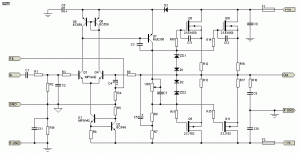
High HiFi Power Amplifier with MOSFET

Circuit amplifier "High Power HiFi Power Amplifier With MOSFET" is capable of giving the output power to the load speakers 240Watt and 380Watt 8Ohm to load 4Ohm speakers.

Voltage source to a series of power amplifiers "High Power HiFi Power Amplifier With MOSFET" This is a CT 25V 50V 25V to 50V CT of transformer CT. In making this power amplifier needs to be installed heatsinks on the power amplifier (MOSFET) in order to avoid excessive heat. The series of power supply to power amplifer can use the transformer 5A-20A and 35A mounted diode bridge and capacitors for a minimum of 2x 10.000uF electrolit. Details for the power amplifier circuit can be seen in the following figure.


High HiFi Power Amplifier with MOSFET

High Power Series HiFi Power Amplifier With MOSFET can modify to increase power output by doubling the final power amplifier is based on the diiginkan. Power generated from doubling the final power amplifier will also double its power output of power amplifier circuit "High Power HiFi Power Amplifier With MOSFET" it.
Continue[...]

Sunday, November 24, 2013

Stereo 9 Volt power amplifier circuit

Here I will explain about the necessary voltage and power amplifier output. The voltage should have at least approximately 9Volt 30Volt voltage and maximum voltage on the DC current. For maximum output of 2 X 2Watt with impedance 8-16 ohm. Because this amplifier circuit using ic and ic is used have the equation, so that if used different ic, then the required output voltage and also differ depending ic respectively.

Part List :
Resistor
R1 = 1M
R2 = 1M
R3 = 1K
R4 = 1K
R5 = 100K
R6 = 100K
R7 = 1R
R8 = 1R
Capacitor
C1 = 1uF
C2 = 220uF
C3 = 1uF
C4 = 100uF
C5 = 5uF
C6 = 5uF
C7 = 0.1uF
C8 = 220uF
C9 = 220uF
C10 = 0.1uF
IC
U1 = ULN2274B , ULN2277 , ULN2278B
Continue[...]

Saturday, November 9, 2013

200 Watt Power Amplifier STK4050 STK4046

Amplifier circuit with IC STK is tough and good quality. In this article an amplifier circuit with IC STK another base. Power "Amplifier 200Watt By STK4050" is an audio amplifier of the STK family with 200Watt power. To create a power amplifier with the STK4050 IC is not require many external components.


Power Amplifier uses symmetric 30Volt power supply system. Power Amplifier With this STK4050 can reproduce the power 200 Watts at 8 Ohm load spaker. In making Power Amplifier 200Watt With this STK4050 do not forget to provide adequate heat sink for the IC STK 4050 in order to avoid overheating.


Schematics Amplifier STK4050-STK4046


PCB Layout Amplifier

Series Power Supply for Power Amplifier 200Watt By STK4050 been displayed in one image with a series of "Power Amplifier" 200Watt With STK4050 above. IC STK 4050 in this series there are several types on the market including STK4050II, STK4050V and STK4050.

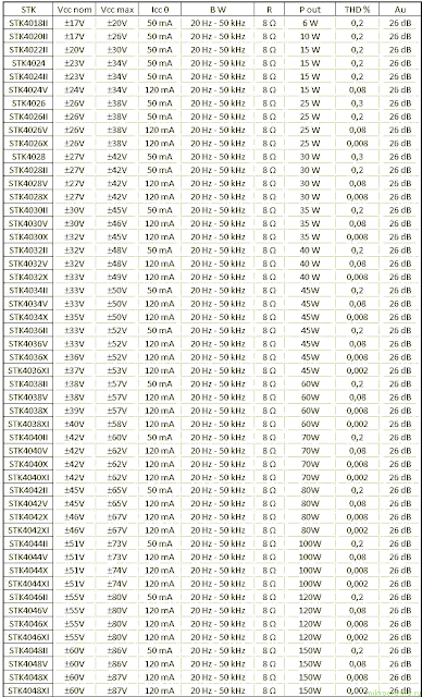
And below is a list of STK ICs are used for a good quality amplifier.

Datasheet STK IC Amplifier
Continue[...]

Thursday, November 7, 2013

Emergency Power Generator Source


Nearby are many period as soon as even more power generator is looked-for, but not free. If an outlet is not inside spread otherwise plugging into the control panel cigarette lighter is simply not an option, youll happen content with the aim of you partake of the Xantrex Powerpack 600HD. This 600-watt device is an all-in the field of-individual constituent so as to is not merely powerful adequate to start your car, but robust enough to provides portable power in support of miniature appliances -- it even comes with a built-in air AM/FM means of communication and digital timepiece.

Runs Multiple Appliances on a long time ago
With three AC outlets and lone DC socket by your fingertips, the 600HD is the completely power solution meant for nation with demanding applications or else the need to run multiple tons all together. custom it to drive slight power tools or else on your outside worksite so you can cause the piece of work ready even exclusive of an outlet nearby. It wish in addition charge cell phones so you can stay connected.

Built-in vogue AM/FM data lines
This thing too has an integrated AM/FM radio and digital alarm control to provides access to harmony, negotiate data lines and news, weather, and imperative in turn in decisive emergency situations.

Rechargeable Battery
The XPower Powerpack 600HD is powered by a sealed, non-spillable 28AH battery to facilitate can be alive conveniently revitalized from every household AC outlet before DC cigarette-lighter outlet so with the purpose of it can be made willing anytime, anywhere.

Inordinate in support of Outings
The Powerpack 600HD isnt a minute ago for era of need. It is just what the doctor ordered for taking on camping trips before outings everywhere approximately trimming power is wanted to run camcorders, film games, televisions, even your espresso contraption.

Safety Mechanisms
The highlight-rich Powerpack 600HD has a built-all the rage 600 watt inverter and a reverse polarity detector to prevent accidentally clamping the cables on top of the mistaken terminals. A barragraph LED indicator monitors the Powerpacks battery charge level, so it wont take advantage of, and an audible alarm signals element overheat and battery under-voltage conditions. An overload and above-warmth protection is built wearing to ensure longer inverter life.Whether its a trade place or else a camp site, the XPower Powerpack 600HD is the ideal portable power solution. 

With three AC outlets and individual DC socket on your fingertips, the Xantrex 600HD is the desirable power solution on behalf of associates with demanding applications otherwise the need to run multiple tons concurrently. make use of it to direct minute power tools before on your outside worksite so you can step the profession through even exclusive of an outlet nearby. It preference in addition charge cell phones so you can stay connected. This item also has an integrated AM/FM broadcasting and digital alarm regulator with the intention of provides access to melody, chat radio and news, weather, and imperative in turn taking part in important emergency situations.

Continue[...]

Saturday, November 2, 2013

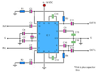
Power amplifier for FM radio receiver

Schematic  is suitable for use in radio tuner or FM radio receiver when it is assembled and ready for use. Where if the low gear power radio receiver, with the aid of power amplifier is less powerfull voice / hard to better and just right. For use hios  speakers , use a low-power , because power amplifier has only the power output of 2 X 5 Watt stereo power amplifeir with impedance of 4 Ohm. Working on a minimum voltage of 4.5 Volts and maximum of 16Volt. Use the correct voltage supply - really have been filtered out in order to improve the performance of these power amplifiers.
TA power amplifier
Component Description :

Resistor
R1________180R
R2________180R
R3________18K
R4________18K

Capacitor
C1________47uF
C2________4.7uF
C4________100uF
C5________100uF
C6________47uF
C7________4.7uF
C8________47uF
C9________100uF
C10_______100uF
C11_______1000uF
C12_______1000uF
C13_______100pF
C14_______100pF
C15_______68n
C16_______68n

IC
IC1_______TA7215P
Continue[...]

Monday, October 28, 2013

Dual Power Supply Circuits

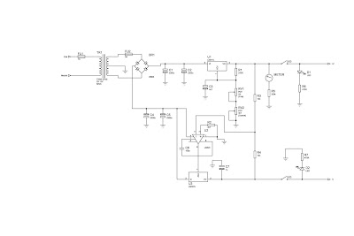
This is a bench top power supply that can be used to power circuits or devices during development work in the lab. More specifically it is an adjustable, tracking, dual rail supply which means there are two supply voltages, one positive, one negative, that are adjusted by a common potentiometer such that supply voltages are equal in magnitude. It is capable of supplying up to +/- 15V DC at up to 1A. This is sufficient for the majority of small signal electronic projects.

Dual Power Suplly Circuit diagram.
Dual Power Supply Circuits
Click to view larger


Power Supply circuit above shows the circuit layout for this project. A centre tapped transformer (TR1) is used with two 12V secondary windings with its centre tap tied to ground. This allows positive and negative voltages to be generated with respect to the central ground. Rectification follows based upon the bridge rectifier (BR1) and smoothing capacitors (C1, C2, C4 and C5).

Two linear regulators are used, an LM317 on the positive side and an LM337 on the negative side. These regulators keep the supply voltage constant for a varying load up to a load current of around 1A. The voltage adjustment is achieved through potentiometers RV1 and RV2 in the positive side of the circuit. The clever part of this circuit comes from the mirroring of the positive voltage adjustment to the negative side via the op-amp U2 to give the circuit its tracking nature.

The op-amp U2 has its positive input tied to ground via a 4K7 resistor. This means that, providing there is negative feedback around the op-amp, the op-amp will endeavour to make its negative input also at ground or 0V. The negative feedback is arranged by the output of the op-amp U2 driving the Adjust pin of the negative regulator U3 and by resistors R3 and R4. The op-amp U2 sets the voltage on the adjust pin of U3 such that the voltage at its negative input is 0V. Also as R3 and R4 are equal, the positive and negative regulated voltages must then be equal in magnitude.

An analogue meter is driven from the positive side to give an indication of the voltage setting. Two switches are used to allow the positive and negative supplies to be turned on/off independently and there are also two LED acting as indicators.

Dual Power Supply Construction

This power supply circuit was built up on Veroboard as it is quite simple to build. Heatsinks can be mounted to the two regulators to improve the current drive capability. The transformer and circuit were mounted inside a wooden box. If a metal box is used the box must be connected to mains earth to prevent a shock hazard. Figure 2 shows a picture of the finished unit. It should be noted that this box is rather shabby and the author has been meaning to improve it for a while but it does do the job nicely.
Continue[...]

Sunday, October 27, 2013

High current output switching power supply

This is low voltage high-current ouput , switching dc power supplly wiht input 220 Volts AC , In this circuit , an St2 diac relaxation oscilator, Q3 , C1 , and the diac , initiates conduction of the output switching transistor Q1, the on time of which is maintained constant by a separate timing / commutation network consisting of Q2 , C2 ,SUS , and SCR 1. See schmeatic diagram below :
The output voltage , consequently , is independent on the duty cycle . To compensate for unwanted variations of output voltage because of input voltage or load resistance fluctuations , an H11C wired as a liniear - model unilateral pnp transistor in a stable different amplifier configuration is connected into the galvanically isolated negative- feedback loop.
Continue[...]

Wednesday, October 23, 2013

6 5W audio power amplifier

This amplifier circuit based on the ic, and the use here is that where ic STK4017 IC has output power of 6.5 watts with the impedance 8Ohm. Minimum required supply voltage and maximum 20Volt 35 Volt DC.
Component
R1 = 100K
R2 = 2K7
R3 = 27R
C1 = 22uF
C2 = 100uF
C3 = 100uF
C4 = 100uF
C5 = 100uF
C6 = 47uF
C7 = 330uF
C8 = 100uF
U1 = STK4017
Besides using STK4017 ic, ic and can use that I mentioned the following:
STK4019
STK4021
STK4023
STK4025
Continue[...]

Sunday, October 13, 2013

LM4651 and LM4652 170W power amplifier

170 Watt power amplifier is a power amplifier that is built by IC LM4651 and LM4652.

Part of this power amplifier driver using the LM4651 IC designed specifically for the purpose of the class AB amplifier driver with short circuit protection feature, containing under voltage, thermal shutdown protection and standby functions. Section 170 Watt power amplifier using LM4651 IC with a MOSFET power amplifier is equipped with temperature sensors that will be used by IC LM4651 as controlnya thermal signal. IC IC LM4651 and LM4652 are designed specifically to each other in pairs to create a class AB power amplifier with protection features are detailed. Detailed series of 170 Watt power amplifier can be seen in thethe following figure .

LM4651 and LM4652 170W power amplifier

Power amplifier circuit requires supply voltages +22 V DC symmetrical 0-22V. Power Amplifier with IC LM4651 and LM4652 are often used in portable HiFi systems such as powered speakers, power subwoofer and car audio power Booter. D1, D2, D3 and D4 in series 170 watt power amplifier with LM4651 and LM4652 is a 22V zener diode.
Continue[...]

Wednesday, October 2, 2013

Ultra Low Power LCD Indicator

This circuit serves as an ultra-low power replacement for multiple LED on-off indicators. It also has the advantage of being easy to read in full daylight. With the parts shown, it is possible to display four bits of information.


The display that I used has three digits and 2 decimal points for a total of 23 segments. Different groupings of segments can be used for the four indicators. I chose to use three squares (shown) and the three lower segments together (not shown) for the four indicators. Many other combinations could be used, one possibility would be to hard-wire numbers or letters out of each of the digits. Other LCD displays could also be used for different effects.

Circuit Diagram


A part that doesnt exist as far as I know, but should, is a single pixel LCD indicator (2 wire). An LCD manufacturer could probably make a lot of money with such a part. If such a thing exists, Id love to hear about it.

Specifications:
Operating Voltage: 3-15V (5V Nominal) DC
Operating Current: 250 microamps to 1 milliamp (400 microamps at 5V)
Operating Frequency: approximately 60 Hz

Theory:
The 7555 IC (CMOS 555 timer) generates a square wave clock signal at approximately 60 hz. This signal is sent to the LCD backplane and the inputs of the four CMOS 4070 XOR gates. If the other input (ind*) of an XOR gate is low, the gates output is a square wave that is in phase with the clock signal. If the ind* input is high, the gates output is out of phase with the clock.

Sending a signal to an LCD segment that is in phase with the backplane signal causes the display to stay blank. Sending an out of phase signal to the LCD segment causes an AC waveform to be applied to the segment which turns it black. Multiple segments are wired in parallel to generate the desired display patterns. The LCD segments require a tiny amount of current to operate, the CMOS gates also take very little power, hence the efficient nature of the circuit. It is necessary to tie the unused segments to the LCD backplane, otherwise they may partially turn on.

If more dislay bits are needed, additional XOR gates can be connected in the same manner. Up to 23 XOR gates could be used to drive the entire display, but a microprocessor and driver software would probably be easier to put together. By generating all of the signals with a microprocessor, all of the driving circuitry can be eliminated.

Other logic families could be used to make this circuit, it should work with a standard 555 timer chip and a 74LS86 XOR gate (different pinout), for example.

Some LCDs may not operate at very cold temperatures, an engineer at Lumex said that their components will work from -30C to +75C.

Construction:
The circuit was built on a standard prototyping plug board. All of the parts can be purchased for under ten dollars.

Use:
The four inputs of the CMOS 4070 IC can connect to outputs on a microprocessor, or any other logic output that needs monitoring. The supply voltage of this circuit should be the same as the driving logics supply voltage.

Parts:
1X Lumex LCD-S301C31TR 3 digit LCD display (from Digi-Key), or equivalent
1X CMOS 4070 quad XOR Gate, a CMOS 4030 should also work.
1X 7555 CMOS 555 timer chip
2X 100nF capacitor
1X 100uF 25V electrolytic capacitor
1X 10K 1/4W resistor
1X 100K 1/4W resistor

Continue[...]

Thursday, September 22, 2011

3V DC to 5V DC REGULATED POWER SUPPLY ELECTRONIC DIAGRAM


3V DC to 5V DC REGULATED POWER SUPPLY ELECTRONIC DIAGRAM

A 5V DC regulated output from 2 cells 3V DC batteries. The output current of the circuit is limited to 50mA. However, it still able to supply many microcontroller circuits. 3009 and 560R Resistor provide the 5V DC output, make up a voltage divider network.
Continue[...]