Showing posts with label high. Show all posts
Showing posts with label high. Show all posts
Tuesday, December 10, 2013
Wideband Two Pole High Pass Filter Schematic
The circuit provides a 10MHz cutoff frequency. Resistor R3 ensures that the input capacitance of the amplifier does not interact with the filter response at the frequency of interest. An equivalent low pass filter is similarly obtained by capacitance and resistance transformation.
Wideband Two-Pole High-Pass Filter Schematic

Wideband Two-Pole High-Pass Filter Schematic

Tuesday, December 3, 2013
High HiFi Power Amplifier with MOSFET
Circuit amplifier "High Power HiFi Power Amplifier With MOSFET" is capable of giving the output power to the load speakers 240Watt and 380Watt 8Ohm to load 4Ohm speakers.
Voltage source to a series of power amplifiers "High Power HiFi Power Amplifier With MOSFET" This is a CT 25V 50V 25V to 50V CT of transformer CT. In making this power amplifier needs to be installed heatsinks on the power amplifier (MOSFET) in order to avoid excessive heat. The series of power supply to power amplifer can use the transformer 5A-20A and 35A mounted diode bridge and capacitors for a minimum of 2x 10.000uF electrolit. Details for the power amplifier circuit can be seen in the following figure.
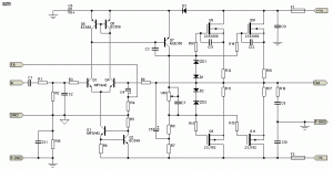
High Power Series HiFi Power Amplifier With MOSFET can modify to increase power output by doubling the final power amplifier is based on the diiginkan. Power generated from doubling the final power amplifier will also double its power output of power amplifier circuit "High Power HiFi Power Amplifier With MOSFET" it.
Sunday, October 27, 2013
High current output switching power supply
This is low voltage high-current ouput , switching dc power supplly wiht input 220 Volts AC , In this circuit , an St2 diac relaxation oscilator, Q3 , C1 , and the diac , initiates conduction of the output switching transistor Q1, the on time of which is maintained constant by a separate timing / commutation network consisting of Q2 , C2 ,SUS , and SCR 1. See schmeatic diagram below :

The output voltage , consequently , is independent on the duty cycle . To compensate for unwanted variations of output voltage because of input voltage or load resistance fluctuations , an H11C wired as a liniear - model unilateral pnp transistor in a stable different amplifier configuration is connected into the galvanically isolated negative- feedback loop.
Saturday, October 26, 2013
High Efficiency White LED Driver Using with NCP5680
This white LED Driver circuit project is based on the NCP5680 high efficiency white LED Driver ic. NCP5680 supports double power flash LED and torch operation . The built-in DC/DC converter is based on a high efficient charge pump structure with 1X, 1.5X and 2X operating modes. The NCP5680 controller is designed to properly drives large external NMOS device with accurate control of the peak current flowing into the LED. Also, the NCP5680 chip includes Open Load and Overload Detection circuit to protect the system against faults at Vout or LED level.
High Efficiency White LED Driver Circuit diagram

Main features of the NCP5680 are : 2.7 to 5.5 V Input Voltage Range , Dual Power Flash LED Capability , Integrated Overload Protection , Selectable Flash/Torch Mode of Operation , Programmable SuperCAP Re−cycling Current , Capable to Share the DC Voltage to Supply Peripheral Circuits , Indicator LED Function , Integrated Photo Sense Function , Support Camera Strobe , Built−in Short Circuit Protection , Selectable Flash Time Out Safety Timing , Support External NMOS up to 10 A Load Capability , Fully I2C Protocol Compliant , Support GSM Synchronization , Built-in LED Test Function.
High Efficiency White LED Driver Circuit diagram
Friday, October 18, 2013
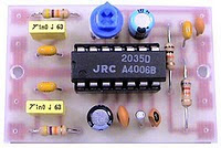
NJM2035 High Quality Stereo Encoder
High Quality Stereo Encoder with NJM2035

Technical Specifications:
Supply Voltage: 1.2V - 3.6V MAX
Current Draw:> 3mA
Channel Separation: <25 dB
Signal to Noise Ratio: 67 dB
Operation Temperature: -20 - 75 ° C
Frequency Range: 20Hz - 15KHz
Component List:
R 2x 47K
R 1x 10K
R 1x 82K
VR 1x 50K POT
C 1x 33uF
C 1x 10uF
C 3x 100nF (104)
C 1x 100pF (101)
C 1x 10pF (10)
1x IC IC NJM2035
1x XT 38 KHz Crystal
Continue[...]
This stereo encoder is the perfect solution for those looking for transmitting high quality stereo sound with low cost. This stereo encoder produces crystal clear stereo sound very good and very good channel separation that can match many more expensive stereo encoders that are available in the market.
Its all possible thanks to 38KHz quartz crystal that controls the 19kHz pilot tone, so youll never go back to calibrate or adjust sirkuit.NJM2035 offer superb quality and manufactured by NJR CORPORATION (JRC), a subsidiary of New Japan Radio, a company known as the worlds best manufacturers of high end professional audio semiconductors. This transmitter will work with mono FM transmitter including the TX300 and TX500 are available on our website. The entire series can easily fit on a small "x 1.5" printed circuit board that allows to adjust in a place where space is limited. While building your stereo encoder please take your time and always check with the scheme to ensure that all connections are done correctly.
Technical Specifications:
Supply Voltage: 1.2V - 3.6V MAX
Current Draw:> 3mA
Channel Separation: <25 dB
Signal to Noise Ratio: 67 dB
Operation Temperature: -20 - 75 ° C
Frequency Range: 20Hz - 15KHz
Component List:
R 2x 47K
R 1x 10K
R 1x 82K
VR 1x 50K POT
C 1x 33uF
C 1x 10uF
C 3x 100nF (104)
C 1x 100pF (101)
C 1x 10pF (10)
1x IC IC NJM2035
1x XT 38 KHz Crystal
How it Works
Stereo encoder consists of three main stages, pre-emphasis, digital encoder and mixer stages.
Pre-emphasis stage is achieved by using two 47K resistors and two capacitors 1NF. This helps to eliminate noise generated during the FM transmission of your audio signal.
The second stage is built around NJM2035 is a digital encoder. All internal blocks except for two audio amplifiers (pins 1 & 14) which acts as a separator made using digital circuits. The first digital circuit is a 38KHz oscillator generated by using external 38KHz crystal (pin 7), 10pF capacitor (pin 6) and 100pF bypass capacitor (pin 5). After 38KHz frequency generated is then buffered and divided into two 19KHz signals with a 180 degree phase difference. Once it is done two frequencies associated with two time division switching MPX digital alternating, one for each audio channel. Heres the audio channel is switched between each other with a total frequency of 38KHz. If you will be able to slow this frequency to 1Hz per second you will be able to hear that this trick is all but. During the first half of the two you will hear the left audio channel and in the second half the second you hear the right audio channel. Due to the fact that the channels are activated by a rapid frequency of 38KHz per second our brain can not recognize that this channel is really switched on and accept this as a continuous audio signal. At the same time another signal from the 38KHz oscillator is divided half to 19KHz. This signal is called a PILOT tone because it will help the stereo decoder in the receiver to slice MULTIPLEX signal (mixed L and R audio channels) and separate them back to the left and right channel audio.
The third stage is a mixer which consists of 33uF and 100nF capacitors and resistors are 82K and 10K. The role of this circuit is to mix the multiplex subcarrier and pilot signals together. The subcarrier multiplex signal coming out of Pin 9 of IC NJM2035 is the sum and difference of both left and right audio channels are activated at 38Khz. PILOT signal coming out of the pin 8 is the frequency of 19KHz that is used to distinguish what channel is currently switched on and without decoding stereo that will not be possible.
Friday, October 11, 2013
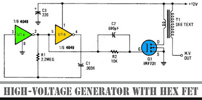
Circuit High Voltage Generator with HEX FET
The schematic diagram below show a circuit of high voltage generator. This circuit uses a 4049 hex inverter as an oscillator, and you can use ignition transformer from automotive engine. A fly-back transformer is possibly usable too. The 4049 will drive the IRF731 HEX FET. The Q1 must be heatsinked. Here is the schematic diagram of the circuit:
Sunday, October 6, 2013
High Gain Crystal Earphone Amplifier
 High Gain Crystal Earphone Amplifier
This simple, one-transistor amplifier provides a voltage accretion over 1000 (60 dB) for active a aerial impedance bowl (crystal) earphone. The aerial accretion is accomplished by replacing the acceptable beneficiary resistor with an abnormal constant-current diode that food 1/2 mA yet exhibits a actual aerial attrition to the audio. This amplifier will accord accomplished array life, cartoon alone 500 uA.
Below is a archetypal appliance application it with the aboriginal clear radio ambit on this page. The amplifier provides acceptable aggregate with a bashful antenna. You may appetite a aggregate ascendancy as with the TL431 project! Or use the Crystal Radio RF Amplifier directly above for even more sensitivity with less than 2 mA current drain.

Subscribe to:
Posts (Atom)