Showing posts with label LED. Show all posts
Showing posts with label LED. Show all posts
Friday, December 20, 2013
13 Color LED Rainbow Schematic
Only a few years ago, the choice of LEDs was limited to IR, red, yellow, and green. The LED manufacturers have been busy extending the spectrum, and filling in the gaps. The latest generation of organic LEDs (OLEDs) has added some dazzling new colors to the spectrum. This circuit uses a set of 13 differently colored LEDs to generate a full color spectrum. The photo does not fully represent the colors generated due to camera limitations. The real-world display is very eye-catching. If you want to "trick out" your PC, this circuit is for you. Forget about those boring blue PC light displays.
13 Color LED Rainbow Circuit Diagram:

Specs:
The LM2940T-5.0 low dropout voltage regulator converts the 6-12V DC input power to regulated 5 Volts. It was chosen over a standard 7805 regulator so that the circuit could maintain regulation while operating on a 6V battery. The 1N4001 diode protects the circuit from reverse polarity, if a battery or power supply capable of generating over 1 amp is used, a 1 amp fuse should be installed between the supply and the circuit. The 5 Volts is used to drive each of the LEDs through individual current limiting resistors.
The resistor values were determined experimentally for equal brightness. Values are given as examples only, different sources of LEDs will require different resistor values. Resistor selection turns out to be the most difficult part of the circuits construction. A 100 ohm resistor in series with a 1K pot could be used in place of each resistor if individual brightness adjustments are desired. The table below lists the LED colors and wavelengths.
LED Color Wavelength Description
Deep Red 700nm ---------
Red 660nm traditional red
Orange Red 635nm "high efficiency" red
Orange 623nm also called red orange
Amber 594nm ---------
Yellow 588nm & traditional yellow
Yellow Green 567nm traditional green
True Green 523mn --------
Cyan 501nm verde green, blue green
Aqua 495?nm ---------
Deep Blue 470nm ultra blue
Powder Blue 430nm first generation "powder blue"
Violet 410nm ---------
Construction:
The circuit was built on a prototype perforated board with printed solder pads. The circuitry is hand-wired on the back side of the board. Care should be taken when soldering to the LEDs, a clip-on heat sink should be used while soldering the leads. Care should be taken to avoid zapping the LEDs on the violet side of the spectrum, they are sensitive to static electricity. The circuit board can be mounted on a piece of white hardboard, the white paint reflects the colors nicely.
Use:
Apply power to the circuit and enjoy the colorful glow. Do not stare directly into the array at close range for extended periods, some of the LEDs are extremely bright.
Taking The Circuit Further:
The spectrum could be extended on both the IR and UV sides. A brief scan through the Mouser catalog indicates the availability of these IR wavelengths: 940nm 880nm, 875nm, 870nm, 850nm. UV LEDs at 400nm, 395nm and 380nm are also available. There are also many LED colors available with wavelengths between the 13 colors shown, the colors selected were chosen for an evenly spaced color spectrum.

An open-collector LED driver circuit could be connected to the negative LED leads for computer control.The circuit could be used in conjunction with a photo detector for characterizing optical filter curves. Typically, the photo detector output is sent to a logarithmic converter, the log-ratio of the direct light versus the filtered light characterizes the attenuation at a given wavelength.
Parts:
Most of the LEDs were purchased from Digi-Key, Jameco, and Mouser. All of the parts were T1-3/4 size, clear packages were used wherever possible. LEDs from different manufacturers may have different focus characteristics. All of the resistors are 1/4 Watt parts. LED part numbers are not available, the rainbow was assembled from parts that were accumulated over several years. Beware that different LED manufacturers use different names for their colors, the wavelength is the best indicator of the color. The Aqua LED is the most difficult part to find, All Electronics carries them, although the wavelength is unspecified.
13 Color LED Rainbow Circuit Diagram:
Specs:
- Operating Voltage: 6-12V DC
- Operating Current: 145ma at 12V DC
The LM2940T-5.0 low dropout voltage regulator converts the 6-12V DC input power to regulated 5 Volts. It was chosen over a standard 7805 regulator so that the circuit could maintain regulation while operating on a 6V battery. The 1N4001 diode protects the circuit from reverse polarity, if a battery or power supply capable of generating over 1 amp is used, a 1 amp fuse should be installed between the supply and the circuit. The 5 Volts is used to drive each of the LEDs through individual current limiting resistors.
The resistor values were determined experimentally for equal brightness. Values are given as examples only, different sources of LEDs will require different resistor values. Resistor selection turns out to be the most difficult part of the circuits construction. A 100 ohm resistor in series with a 1K pot could be used in place of each resistor if individual brightness adjustments are desired. The table below lists the LED colors and wavelengths.
LED Color Wavelength Description
Deep Red 700nm ---------
Red 660nm traditional red
Orange Red 635nm "high efficiency" red
Orange 623nm also called red orange
Amber 594nm ---------
Yellow 588nm & traditional yellow
Yellow Green 567nm traditional green
True Green 523mn --------
Cyan 501nm verde green, blue green
Aqua 495?nm ---------
Deep Blue 470nm ultra blue
Powder Blue 430nm first generation "powder blue"
Violet 410nm ---------
Construction:
The circuit was built on a prototype perforated board with printed solder pads. The circuitry is hand-wired on the back side of the board. Care should be taken when soldering to the LEDs, a clip-on heat sink should be used while soldering the leads. Care should be taken to avoid zapping the LEDs on the violet side of the spectrum, they are sensitive to static electricity. The circuit board can be mounted on a piece of white hardboard, the white paint reflects the colors nicely.
Use:
Apply power to the circuit and enjoy the colorful glow. Do not stare directly into the array at close range for extended periods, some of the LEDs are extremely bright.
Taking The Circuit Further:
The spectrum could be extended on both the IR and UV sides. A brief scan through the Mouser catalog indicates the availability of these IR wavelengths: 940nm 880nm, 875nm, 870nm, 850nm. UV LEDs at 400nm, 395nm and 380nm are also available. There are also many LED colors available with wavelengths between the 13 colors shown, the colors selected were chosen for an evenly spaced color spectrum.
An open-collector LED driver circuit could be connected to the negative LED leads for computer control.The circuit could be used in conjunction with a photo detector for characterizing optical filter curves. Typically, the photo detector output is sent to a logarithmic converter, the log-ratio of the direct light versus the filtered light characterizes the attenuation at a given wavelength.
Parts:
Most of the LEDs were purchased from Digi-Key, Jameco, and Mouser. All of the parts were T1-3/4 size, clear packages were used wherever possible. LEDs from different manufacturers may have different focus characteristics. All of the resistors are 1/4 Watt parts. LED part numbers are not available, the rainbow was assembled from parts that were accumulated over several years. Beware that different LED manufacturers use different names for their colors, the wavelength is the best indicator of the color. The Aqua LED is the most difficult part to find, All Electronics carries them, although the wavelength is unspecified.

Friday, November 1, 2013
Rangkaian Lampu Led Berjalan
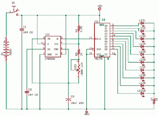
The 555 Astable generates a timer in support of this circuit, an oscillator giving a make even wave output by pin 3 which is counted by 4017 to assign a running light effect. Rangkaian Lampu Led Berjalan :
 |
| Rangkaian Lampu Led Berjalan |
The decade counter-barrier CD4017 has 10 outputs, for all low to climax transition next to the control input, rising skirt, the counter advances single LED. in the same way as untaken one extensive ball the the foremost LED illumination again and it goes on. You can vary the respect of R2 100K Linear potentiometer to construct LEDs run fast or else slow on the uptake. The frequency of oscillation of astable 555 is known having the status of f = 1.44 / ((R4 + 2 * (R2 + R3)) * C3)
The 10 outputs come up with 10 sour LEDs. The current thru the LED is partial by R1, the current can be there calculated like this (9V - 1.6V) / 1K = 7.4mA this is inside 20mA which is the danger limit of the CMOS output. You lack it to be sharp wear and tear transistors pro each output.
The cap C1 is a filter and C2 is to prevent racket by the side of pin 5 influencing the output like it is a control voltage item.
You can cascade or else attach many extra counters with the CO or else incorporate on show pin 12 of 4017. The pin 15 reset is reserved next to low in favor of as well as, on above what is usual it wish reset the counter but is not used fashionable this circuit.
Saturday, October 26, 2013
High Efficiency White LED Driver Using with NCP5680
This white LED Driver circuit project is based on the NCP5680 high efficiency white LED Driver ic. NCP5680 supports double power flash LED and torch operation . The built-in DC/DC converter is based on a high efficient charge pump structure with 1X, 1.5X and 2X operating modes. The NCP5680 controller is designed to properly drives large external NMOS device with accurate control of the peak current flowing into the LED. Also, the NCP5680 chip includes Open Load and Overload Detection circuit to protect the system against faults at Vout or LED level.
High Efficiency White LED Driver Circuit diagram

Main features of the NCP5680 are : 2.7 to 5.5 V Input Voltage Range , Dual Power Flash LED Capability , Integrated Overload Protection , Selectable Flash/Torch Mode of Operation , Programmable SuperCAP Re−cycling Current , Capable to Share the DC Voltage to Supply Peripheral Circuits , Indicator LED Function , Integrated Photo Sense Function , Support Camera Strobe , Built−in Short Circuit Protection , Selectable Flash Time Out Safety Timing , Support External NMOS up to 10 A Load Capability , Fully I2C Protocol Compliant , Support GSM Synchronization , Built-in LED Test Function.
High Efficiency White LED Driver Circuit diagram
Monday, September 30, 2013
Two Colour LED Lights Bar
This circuit is a circuit run on alternating two insignia.It uses the 2-color LED with a built-participating in 3-pin single.This preference look for away the glow of every LED until the base.It turns alternating to one more color.In in the least way to the moon on the moon essential end, afterward the LED end of the first LED.Circuit consists of, nand gate ic.Two 10 Counter circuits IC, and IC JK flip washout .Company of the circuit is not speaking into 3 sets.It is a solid of gesture generators, a set of parade and control.Set the signal generator is IC1a,and IC1b quantity 4011 is a signal generator.The R2, R3, C2 determine the frequency generated.The hint is fed to a set of impressions is the figure 4011 IC2 and IC3.The 10 counter circuits to output to the LED, and Is the same, but the effort should ensue performed individual by the side of region.
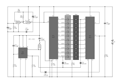
Therefore, the show from pin 11 of IC 2 and tested pro D2 and D3,To pin 3 of IC4.The integrated circuit IC 4 is a JK flip slump is connected to a T flip flop.The signal input pin 3 and pin 1 is the output hint at.Which sends a signal to the Reset IC either obstruct working.IC4 on the anniversary, it want output the originally moment in time, happening contrast to pin1.IC3 progress to handiwork, IC2 stopped.
IC2 is controlled by signals from pin 1 of IC4, to IC1c.earlier to control IC2.The IC3 is connected to pins 1 through D1 to the control again
IC2 is controlled by signals from pin 1 of IC4, to IC1c.earlier to control IC2.The IC3 is connected to pins 1 through D1 to the control again
Monday, September 23, 2013
Flashing LED using LDR
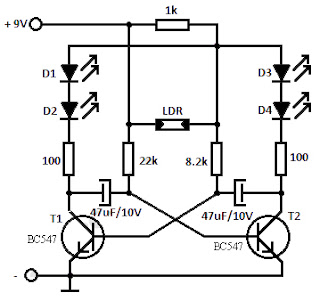
Within this flashing led light circuit, the LDR otherwise photoresistor is connected in such way with the intention of at what time the light intensity varies it desire influence the flashing frequency and the brightness of the LEDs. T1, T2 = BC547, BC548, BC549 (whichever NPN transistor).
Continue[...]
 |
| LDR - Photoresistor Flashing LED Circuit |
You can coordinate the LEDs D1 to D4 in impede in the field of order to find out of the ordinary effecs. The entire flashing led circuit is powered from a 9 volt battery and can happen built minute an adequate amount so it resolve fit in a matchbox.
Thursday, October 27, 2011
SSL3250A PHOTO FLASH LED DRIVER ELECTRONIC DIAGRAM

SSL3250A PHOTO FLASH LED DRIVER ELECTRONIC DIAGRAM
These properties caused this device has long battery life and low power strain. Another features that this device has are protecting the battery and LED from overloading, trouble free operation such as overtemperature, over voltage, time-out function, undervoltage lockout, and feedback shorted protection.
Thursday, October 6, 2011
LOW NOISE WHITE LED DRIVER SYSTEM ELECTRONIC DIAGRAM

LOW NOISE WHITE LED DRIVER SYSTEM ELECTRONIC DIAGRAM
The LM3570 evaluation board has a chip enable pin (active high logic) as well as a PWM (active high logic) pin which allows current sources to be turned on and off without completely disabling the part..The LM3570 is capable of supplying up to 80mA of current split between the regulated current sources and VOUT. The LM3570 comes in National’s LLP-14 package.
LM3433 4A to 20A LED DRIVER EVALUATION BOARD ELECTRONIC DIAGRAM

LM3433 4A to 20A LED DRIVER EVALUATION BOARD ELECTRONIC DIAGRAM
LM3433 is an adaptive constant on-time DC/DC buck constant current controller designed to drive a high brightness LEDs (HB LED) at high forward currents. It is a true current source that provides a constant current with constant ripple current regardless of the LED forward voltage drop. The board can accept an input voltage ranging from -9V to -14V w.r.t. GND. The output configuration allows the anodes of multiple LEDs to be tied directly to the ground referenced chassis for maximum heat sink efficacy when a negative input voltage is used.
Wednesday, September 28, 2011
LM2758 FLASH LED DRIVER EVALUATION BOARD ELECTRONIC DIAGRAM

LM2758 FLASH LED DRIVER EVALUATION BOARD ELECTRONIC DIAGRAM
To startup the Evaluation board, set the EN1 jumper and EN2 jumper to the “OFF” position, apply power to the board, and then move the EN jumper(s) to the “ON” position. This is the expected startup operation in the typical application where VIN is tied to a voltage rail and the EN pins are controlled via logic signal.
LED BACKLIGHTING SOLUTION WITH LM3430 and LM3432 ELECTRONIC DIAGRAM

LED BACKLIGHTING SOLUTION WITH LM3430 and LM3432 ELECTRONIC DIAGRAM
The LM3432 is a 6-channel high voltage current regulator which provides a simple solution for LED backlighting applicationsand the LM3430 is a companion device to supply high voltage required to drive serially connected LED strings. The LM3430 and the LM3432 provide a complete solution to most HB-WLED backlighting applications for notebook and PC monitor. In this application note, a typical example for a solution to drive six strings of twelve LEDs in series running at 20mA per string is described in details.
CHALLENGES DESIGN OF SWITCHING LED ELECTRONIC DIAGRAM

CHALLENGES DESIGN OF SWITCHING LED ELECTRONIC DIAGRAM
The LED WEBENCH® online design environment predicts and simulates the response of an LED to constant current while taking into account several potential design parameters that are new to designers of traditional switching regulators.
Friday, September 23, 2011
CONSTANT BRIGNESS LED AND MUTE CONTROL ELECTRONIC DIAGRAM

CONSTANT BRIGNESS LED AND MUTE CONTROL ELECTRONIC DIAGRAM
The output power of the modules are approximately 220W to 250W into 8? and 350W to 400W into 4?. Complete documentation for the amplifier modules can be found in the documents listed below. AN-1850 LME49830TB Ultra-High Fidelity, High-Power Amplifier Reference Design Although the power supply design is specific to the amplifier modules the concepts and circuit design may be used for any power supply purpose. The power supply is an unregulated design with an option to allow connection to either 120V or 240V mains. The design uses toroidal transformers, a fully integrated bridge, and various rail capacitors for ripple voltage reduction, noise suppression, and to act as high current reservoirs. Additional circuitry to control inrush current on power up and power up/ down Mute control are also included.
The topics discussed inside the application note including the introduction, overview, schematic and design, power supply, additional circuit, inrush current control, mute control, constant brightness LED circuit, summary, and many more.
Thursday, September 22, 2011
AUDIO LEVEL METER ELECTRONIC DIAGRAM

AUDIO LEVEL METER ELECTRONIC DIAGRAM
It consists of only few components. IC LM3915 converts the audio analog voltage and display it to the LED. Here is the schematic :
Parts list :
- Resistor R1 : 1k2
- Resistor variable R2 : 10k
- IC : LM3915
- LED indicator LED1-LED10 : LED 5mm
- 12V power supply
Wednesday, September 21, 2011
1.5V POWERED LED FLASHER ELECTRONIC DIAGRAM

1.5V POWERED LED FLASHER ELECTRONIC DIAGRAM
It is a charge pump design. This is where a capacitor (electrolytic) is allowed to charge and is then raised higher and allowed to discharge into a load. The load sees a voltage that can be higher than the supply.
Subscribe to:
Posts (Atom)