Showing posts with label with. Show all posts
Showing posts with label with. Show all posts
Thursday, January 30, 2014
2 X 50W ICs amplifier with STK4191
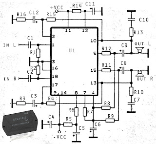
The above is a stereo amplifier circuit based on IC STK4191 with 2 X 50Watt output power 8 ohm impedance. And besides that you can use some of the IC can also be applied in this series include the STK4101, 4111, 4121, 5131, 4141, 4151, 5161, 4171, 4181, and 4191. Required supply voltage from 12 Volt to 35 Volt DC.Part List :
R1 = 22K
R2 = 22K
R3 = 560R
R4 = 56K
R5 = 1K
R6 = 1K
R7 = 100R
R8 = 2K
R9 = 2K
R10 = 4.7R
R11 = 2K2
R12 = 2K2
R13 = 4.7R
R14 = 100R
R15 = 56K
R16 = 560R
C1 = 0.1uF
C2 = 0.1uF
C3 = 100uF
C4 = 100uF
C5 = 100uF
C6 = 0.1uF
C7 = 47uF
C8 = 47uF
C9 = 0.1uF
C10 = 100uF
C11 = 100uF
U1 = STK4191

Sunday, January 26, 2014
Multiplexer with TTL IC 74251
Actually you can not bother to design a multiplexer using logic gates because it has many special IC which functioned for a multiplexer.

One of the TTL ICs from the family that you can use to fulfill the function of a multiplexer is IC 74 251. At the IC there are 8 input channels and 3-bit selector and the other lane as a control reset and inverting output. As a note if you are using TTL ICs for your electronic circuit, the voltage supply that is allowed a maximum of 5 volts. So you can be more familiar with the workings of this multiplexer ic, IC74251 consider the truth table below:
C | B | A | G | Y | W |
X | X | X | 1 | Z | Z |
0 | 0 | 0 | 0 | D0 | D0’ |
0 | 0 | 1 | 0 | D1 | D1’ |
0 | 1 | 0 | 0 | D2 | D2’ |
0 | 1 | 1 | 0 | D3 | D3’ |
1 | 0 | 0 | 0 | D4 | D4’ |
1 | 0 | 1 | 0 | D5 | D5’ |
1 | 1 | 0 | 0 | D6 | D6’ |
1 | 1 | 1 | 0 | D7 | D7’ |
Z = High impedance (off) | |||||
D0,D1…D7 = Representing the output of the input lines D | |||||
Wednesday, January 22, 2014
Digital Clock with Timer and Solar Panel Regulator
This is a combination digital clock timer and solar panel charge controller used to maintain a deep cycle battery from a solar panel. The timer output is used to control a 12 volt load for a 32 minute time interval each day. Start time is set using 9 dip switches and ends 32 minutes later. The 32 minute duration is set by selecting the 5th bit (2^5 = 32) of a 4040 binary counter (pin 2). The timer also has a manual toggle switch so the load can be manually switched on or off and automatically shuts off after 32 minutes. The time duration can be longer or shorter (8,16,32,64,128,256 minutes etc.) by selecting the appropriate bit of the counter. The timer circuit is shown in the lower schematic just above the regulator.
The basic clock circuit (top schematic below) is similar to the binary clock (on another page) and uses 7 ICs to produce the 20 digital bits for 12 hour time, plus AM and PM. A standard watch crystal oscillator (32,768) is used as the time base and is divided down to 1/2 half second by the 4020 binary counter. One half of a 4013 data latch is used to divide the 1/2 second signal by 2 and produce a one second pulse that drives the seconds counter (74HC390 colored purple). The minutes are advanced by decoding 60 seconds (40 + 20) and then resetting the seconds counter to 0 and at the same time advancing the minutes counter. The same procedure is used to advance the hours. The second half of the 4013 latch is used to indicate AM or PM and is toggled by decoding 13 hours and resetting the hours to 0 and then advancing the hours to "one".
The clock display circuit is shown in the second drawing below and uses 6 more ICs to decode the binary data and drive four seven segment LED displays. The 10s of hours digit is driven with a single 3904 transistor. Two multiplexer circuits (4053) are used to manually select either minutes or seconds for the right two display digits. The two switches shown between the 4053s and below the left 4053 are both part of one DPDT switch which selects either seconds or minutes for the 1X and 10X digits. This switch is shown in the seconds position and the hours digits are blanked with a low signal on pin 4 of the 4511.
The display can also be toggled on and off (totally blank) using a set/reset latch made from a couple 74HC00 NAND gates. A momentary DPDT switch is used to control the latch and toggle the display on or off. The second pole of this switch is used on the upper drawing (connected to the run/stop switch) to set the hours and minutes. Thus this same switch performs both functions of blanking the display and setting the time. The run/stop switch is shown in the normal running mode and supplies a low signal to a NAND gate which prevents accidental setting the time while the clock is running.
The run/stop switch also turns on the display (through the diode D2) when in the stop position. The procedure for setting the clock would be to set the (run/stop) switch the stop position and the (seconds/minutes) switch to the minutes position. Then toggle the momentary switch to set minutes and hours of the current time plus one minute. The clock can then be started with the run/stop switch at precisely the right time (+/- 0.5 seconds).
The voltage regulator in the lower drawing maintains the battery at 13.6 volts and also supplies the clock and timer circuits with 4.3 volts. The charge LED indicator only comes on when the regulator is supplying max charge to the battery. When the battery voltage reaches 13.6 the regulator reduces the current to whatever is necessary to maintain the voltage and the charge indicator will turn off. The unit I built also included a battery condition indicator (voltmeter using 4 LEDs) to indicate the battery condition so that a failure of the regulator would be indicated by the charge indicator LED turned off and less than 4 LEDs lit on the voltmeter.
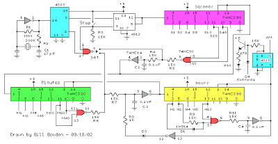 |
| Basic Clock Circuit Diagram |
The basic clock circuit (top schematic below) is similar to the binary clock (on another page) and uses 7 ICs to produce the 20 digital bits for 12 hour time, plus AM and PM. A standard watch crystal oscillator (32,768) is used as the time base and is divided down to 1/2 half second by the 4020 binary counter. One half of a 4013 data latch is used to divide the 1/2 second signal by 2 and produce a one second pulse that drives the seconds counter (74HC390 colored purple). The minutes are advanced by decoding 60 seconds (40 + 20) and then resetting the seconds counter to 0 and at the same time advancing the minutes counter. The same procedure is used to advance the hours. The second half of the 4013 latch is used to indicate AM or PM and is toggled by decoding 13 hours and resetting the hours to 0 and then advancing the hours to "one".
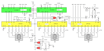 |
| Clock Display Circuit Diagram |
The clock display circuit is shown in the second drawing below and uses 6 more ICs to decode the binary data and drive four seven segment LED displays. The 10s of hours digit is driven with a single 3904 transistor. Two multiplexer circuits (4053) are used to manually select either minutes or seconds for the right two display digits. The two switches shown between the 4053s and below the left 4053 are both part of one DPDT switch which selects either seconds or minutes for the 1X and 10X digits. This switch is shown in the seconds position and the hours digits are blanked with a low signal on pin 4 of the 4511.
The display can also be toggled on and off (totally blank) using a set/reset latch made from a couple 74HC00 NAND gates. A momentary DPDT switch is used to control the latch and toggle the display on or off. The second pole of this switch is used on the upper drawing (connected to the run/stop switch) to set the hours and minutes. Thus this same switch performs both functions of blanking the display and setting the time. The run/stop switch is shown in the normal running mode and supplies a low signal to a NAND gate which prevents accidental setting the time while the clock is running.
 |
| Clock Timer Circuit Diagram |
The run/stop switch also turns on the display (through the diode D2) when in the stop position. The procedure for setting the clock would be to set the (run/stop) switch the stop position and the (seconds/minutes) switch to the minutes position. Then toggle the momentary switch to set minutes and hours of the current time plus one minute. The clock can then be started with the run/stop switch at precisely the right time (+/- 0.5 seconds).
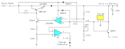 |
| Voltage Regulator (13.6 volts) |
The voltage regulator in the lower drawing maintains the battery at 13.6 volts and also supplies the clock and timer circuits with 4.3 volts. The charge LED indicator only comes on when the regulator is supplying max charge to the battery. When the battery voltage reaches 13.6 the regulator reduces the current to whatever is necessary to maintain the voltage and the charge indicator will turn off. The unit I built also included a battery condition indicator (voltmeter using 4 LEDs) to indicate the battery condition so that a failure of the regulator would be indicated by the charge indicator LED turned off and less than 4 LEDs lit on the voltmeter.
Thursday, January 16, 2014
2 X 50W ICs amplifier with STK4191
The above is a stereo amplifier circuit based on IC STK4191 with 2 X 50Watt output power 8 ohm impedance. And besides that you can use some of the IC can also be applied in this series include the STK4101, 4111, 4121, 5131, 4141, 4151, 5161, 4171, 4181, and 4191. Required supply voltage from 12 Volt to 35 Volt DC.Part List :
R1 = 22K
R2 = 22K
R3 = 560R
R4 = 56K
R5 = 1K
R6 = 1K
R7 = 100R
R8 = 2K
R9 = 2K
R10 = 4.7R
R11 = 2K2
R12 = 2K2
R13 = 4.7R
R14 = 100R
R15 = 56K
R16 = 560R
C1 = 0.1uF
C2 = 0.1uF
C3 = 100uF
C4 = 100uF
C5 = 100uF
C6 = 0.1uF
C7 = 47uF
C8 = 47uF
C9 = 0.1uF
C10 = 100uF
C11 = 100uF
U1 = STK4191
Monday, January 13, 2014
Schematic Audio Amplifier with IC AN5260
This is a simple circuit schematic, you can string up this circuit easily. You just need IC AN5260 with some components such as , Condensator Electrolit , Resistor , Ceramic Condensator . Schematic require voltage 12 to 26 Volt . And i use current voltage of 12 volt. Its nice sound , smooth , and low noise amplifier. You want to try this schematic ? .
See this schematic below :

Datasheet IC 5260
Vcc = 12-26 V
Pout = 6,6 W
RL = 8 Ohm
Ft = 30hz - 18Khz
Icco = 60 mA
Package = SIP2-11
Manufactered = MATSUSHITA
Saturday, January 11, 2014
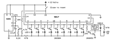
Control Relay Circuit with 9 Second
See figure below its Control Relay Circuit Schematics.
Continue[...]
Wednesday, December 25, 2013
Battery Charger with Temeperature Sensor

Battery with a LM35 temperature sensor on the charger used to monitor the battery temperature is in charge. Battery temperature sensor is needed because the battery temperature will rise at the time in charge. Battery temperature sensor LM35 temperature sensor has high accuracy in monitoring the battery temperature, it is because the temperature sensor LM35 is a temperature sensor that can convert temperature changes into voltage changes linearly.
At the time of the charge a battery will experience changes in temperature, where the battery temperature will begin to rise when the battery began to fill. To avoid over heat the battery, the battery temperature sensor LM35 temperature sensor is required to terminate the battery charging current to avoid overheating.
 |
| Battery charger with temperature sensor schematic |
On the battery charger circuit temperature sensor with temperature sensor 35 lm above the R1 is used for setting the maximum value of the desired temperature. Therefore, when the temperature was in-charge the battery begins to rise and reach temperatures setup then this series will break the current battery charge.
Thursday, December 5, 2013
Quad Audio Amplifier Circuit diagram with TDA7831 4×25W
 Quad Audio Amplifier Circuit diagram with TDA7831 4×25W
The afterward is a cloister amplifier circuit (amplifier with four inputs and four outputs) based TDA7381. This amplifier is advised for car audio system, but you can additionally use this ambit for added purposes. This ambit has a architecture actual simple and actual accessible to build.
Tuesday, December 3, 2013
High HiFi Power Amplifier with MOSFET
Circuit amplifier "High Power HiFi Power Amplifier With MOSFET" is capable of giving the output power to the load speakers 240Watt and 380Watt 8Ohm to load 4Ohm speakers.
Voltage source to a series of power amplifiers "High Power HiFi Power Amplifier With MOSFET" This is a CT 25V 50V 25V to 50V CT of transformer CT. In making this power amplifier needs to be installed heatsinks on the power amplifier (MOSFET) in order to avoid excessive heat. The series of power supply to power amplifer can use the transformer 5A-20A and 35A mounted diode bridge and capacitors for a minimum of 2x 10.000uF electrolit. Details for the power amplifier circuit can be seen in the following figure.
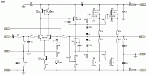
High Power Series HiFi Power Amplifier With MOSFET can modify to increase power output by doubling the final power amplifier is based on the diiginkan. Power generated from doubling the final power amplifier will also double its power output of power amplifier circuit "High Power HiFi Power Amplifier With MOSFET" it.
Saturday, November 30, 2013
6 Watt Audio Amplifier Schematic Circuit with TDA1519
 6 Watt Audio Amplifier Schematic Circuit with TDA1519
The audio amplifier circuit is on the TDA1519 amplifier IC that is based in audio applications, which is not a aerial achievement ability can be used. The ambit TDA1519 is a ability of 2×6 watts.
The TDA1519 is an amplifier congenital Class B dual-output advance in a 9-by-line (SIL) artificial amalgamation boilerplate achievement is primarily developed for car radio applications.
Key Features of the audio amplifier IC TDA1519 are: Requires few alien components, anchored gain, acceptable bounce drive, aphasiac / standby mode, thermal protection, about-face polarity safe. Tda1519 amplifier ability rating, 14.4 volts.
Wednesday, November 27, 2013
Volt meters ampere meter with PIC
Volt meters & ampere meter with PIC can be used to measure voltage and current simultaneously. The series of volt meters & ampere meter with PIC16F876A PIC is used as a data processor voltage and current are measured.
This circuit uses the viewer in the form of 16 × 2 LCD used for the data menmpilkan voltage and current measurements. In the article volt meter and ampere meter with PIC are discussed kerannya limited to devices only. More detail can be seen from the image sequence volt meter and ampere meter with PIC below.
The images of Volt Meter & Ampere Meter With PIC Circuit
 |
| Volt meters & ampere meter with PIC |
Tuesday, November 12, 2013
Track the damage capacitors elco with ESR meter
All technicians must have the same experience that the old models of aircraft generally have several common Elco its dry or down in value, mainly found in many brands of china plane. Eco is dry can cause a variety of disorders that are sometimes difficult to trace or even be able to make certain parts do not work at all, especially if used on a circuit that works at such high frequency SMPS (Switch Mode Power Supply) and the horizontal. Elco dry technicians sometimes make headaches and time consuming when you track the damage.
 Many technicians get around this problem by directly replacing all existing Elko, the Elko-regardless of whether Elko is corrupt or not. It is generally quite successful. But sometimes the quality is not good substitutes Elko, so the damaged aircraft back after use for some time. Replace all of Elko is also a problem for yourself if the circuit is improved a lot using Elko. The use of ESR-meter proved to be the most appropriate choice to solve the above problems. We suggest that ESR-meter is a must-have tool for every technician after avo-meter.
Using ESR-meter weve made themselves at a cost of less than 50,000 rupiah we recorded a lot of advantages such as:
- Elko track damaged by the time more quickly because they do not need to remove the Elko (in-circuit tester) one by one.
- Elko only replaced damaged
- Can be used to check the quality of new and used Elko. It is certainly advantageous to utilize part of the former ex-change machine pcb. Sometimes the plane is damaged due to repeated just posted a new Elko was poor quality.
- Elko that if the check using the ohm-meter sometimes the results are deceptive. Because if you checked with ESR ESR-meter turns his already large.
- Can be used to check the flyback is short in the primary coil (between the B + with a pin-pin-collectors), def a short yoke, the power tranfo a short primer.
- To find out if re-chargeable batteries are still good. Re-chargeable battery that is damaged ESR was generally higher when compared to a still good.
- To keep track of printed lines leaking / short
- By comparing the capacitors are still good, ESR-meter can be used to check the value of thousands pf capacitor.
Note:
- ESR meter can not be to find Elko leak or short. Fortunately rare short Elko damage.
- ESR meter to check the fit only Elko with values ranging 0.47uF and above.
Does ESR it actually? Parameters are generally owned by a Elko understood by engineers is the "maximum working voltage" and "capacitance value". In the real case there are several other parameters such as the "maximum working temperature" (85 or 105 degrees C) and "ESR" (Equivalent Series Resistance). Unless the practice is capacitive in Elko also has the characteristics of "resistive" caused by a combination of resistance to the legs, internal connections, plates and electrolyte. Thus form a resistive characteristic ESR, because if it is portrayed as if such be installed in series with the capacitance of Elko. Ideally, an Elko ESR is zero, but in practice this is impossible. Elko High voltage tends to have larger ESR than the low voltage Elko Elko with small values tend to have higher ESR values greater than Elko. Elko 105 degrees (C) tend to have higher ESR than Elko 85 degrees (C).
What Is the ESR-meter?
ESR meter is a kind of ohm-meter that can be used to measure the amount of "resistance" of Elko. Difference if the ohm-meter using a dc current (direct current) to drive the meter, then use the ESR meter ac (alternating current) with a standard frequency 150Khz. As had been explained that ideally Elko its ESR is zero. But this is not possible in practice. Elko good quality 10uF value is close to zero or more generally.
What is the cause of ESR Elko subject to change.
- The first is caused because of the connection quality is poor constituents. It can be found in Elko Elko New and old.
- Both are caused due to dry the liquid electrolyte due to evaporate or leak, which can be found at the old Elko. Are the consequences of large ESR Elko turned into?
Consequences of changing the value of ESR Elko
- Elko is a working principle can be "in-fill and waste of" electric charge repeatedly. Thus ESR Elko-charging current will be passed this exile repeatedly in accordance with the working frequency of the circuit. And we certainly have understood that if bypassed resistor will generate heat flows in accordance with the magnitude of the current strength through resistance value and the corresponding magnitude. Similarly, the Elko with ESR, the greater the greater the ESR value of the heat arising in Elko, and the higher the frequency the greater the heat generated. This heat can eventually cause the electrolyte evaporates into a gas and seeped out, so the value of Elko will turn down. In the specific cases heat can even make Elko explode.
- On a circuit that works at high frequencies Elko should have zero resistance to the high frequency signal. If the ESR of the resistance turned into Elko is no longer zero, and if the resistance value change is large enough to make the workings of the chaotic circuit.
Our experience with the use of ESR meter in the aircraft repair older model (the old plane), the first one we always do is:
- Check out all the Elko with ESR-meter at the SMPS, Horizontal and Vertical and immediately replace it if the ESR problem.
- Check visually (with a magnifying glass if necessary) solder-solder on the SMPS, the output Horizontal, Vertical output, and the CRT socket pcb and soldering again if there appears a problem or suspicious solder it.
- Both of these were able to eliminate the difficulties that may arise and difficult to trace, so the use of ESR meter can shorten repair time.
How to use homemade ESR meter (calibration)
- Once the tool is finished
- Collect some old Elko is still good. Find Elko pcb traces of the plane, made in Japan or Europe the original (former aircraft engine change) because of generally good quality for use as a reference.
- Grouped on the basis of a value less dar 2.2uF, 4.7uF is less than, less than and greater than 10uF 10uF.
- Try using the ESR-meter to measure each group, and mark the position of the needle meter on each group
- These markers can be used as a reference to the appointment of Elko ESR is still good.
- If the meter needle to deviate less from the reference mark, the mean ESR Elko is not good.
Saturday, October 26, 2013
High Efficiency White LED Driver Using with NCP5680
This white LED Driver circuit project is based on the NCP5680 high efficiency white LED Driver ic. NCP5680 supports double power flash LED and torch operation . The built-in DC/DC converter is based on a high efficient charge pump structure with 1X, 1.5X and 2X operating modes. The NCP5680 controller is designed to properly drives large external NMOS device with accurate control of the peak current flowing into the LED. Also, the NCP5680 chip includes Open Load and Overload Detection circuit to protect the system against faults at Vout or LED level.
High Efficiency White LED Driver Circuit diagram

Main features of the NCP5680 are : 2.7 to 5.5 V Input Voltage Range , Dual Power Flash LED Capability , Integrated Overload Protection , Selectable Flash/Torch Mode of Operation , Programmable SuperCAP Re−cycling Current , Capable to Share the DC Voltage to Supply Peripheral Circuits , Indicator LED Function , Integrated Photo Sense Function , Support Camera Strobe , Built−in Short Circuit Protection , Selectable Flash Time Out Safety Timing , Support External NMOS up to 10 A Load Capability , Fully I2C Protocol Compliant , Support GSM Synchronization , Built-in LED Test Function.
High Efficiency White LED Driver Circuit diagram
Tuesday, October 22, 2013
DAC with MCS5 Microcontroller

Digital scale is given to the B1 to B7 (leg 5 to 12) in the IC DAC0800, the binary value of the digital scale was converted into an analog magnitude of the current at IOUT (ft 4 DAC0800) and IOUT * (feet 2 DAC0800), then by IC Operational Amplifier LM741 flow is converted into voltage. The resulting voltage expressed by the formula shown in Figure below, in addition to depending on a digital scale weight value is given, this voltage depends on the size of Vref (DAC0800 14 feet).
 |
| figure.1 DAC With MCS5 Microcontroller |
C3 is mounted on leg 16 and ground is useful for stabilizing the voltage generated. DAC0800 and LM741 using voltage source +12 Volt and -12 Volt, is somewhat different from the voltage that is usually used for digital circuits, so that digital signals can be received well IC DAC0800, DAC0800 equipped foot VLC (pin 1) for various voltage levels menyesesuaikan types of digital ICs. In the DAC0800 data sheet are shown in various series to be installed on this leg for DAC0800 can be used for a variety of digital IC family. In the circuit of Figure above, the DAC0800 is connected to the microcontroller MCS51 family who work at TTL voltage levels, for this purpose VLC leg connected to ground.
Behind the legs of the IC DAC0800 B1 through B8 are not equipped to accommodate a latch that is fed a digital scale, changing the combination of digital signals on the legs is a direct result of output voltage change. Construction inputs such DAC0800, DAC0800 result can not be connected directly to a channel-data (data bus) microprocessor system, the relationship DAC0800 to the processor must pass through the parallel port.
In Figure 1, the DAC0800 is connected to the parallel port P1 from AT89Cx051. Connecting the DAC0800 to the other MCS51 family, for example AT89C51, can pass parelel ports P0, P1, P2 or P3, depending on the conditions established series. Instructions to remove the voltage in the circuit of Figure 1 is very simple, just use instruction MOV P1, A analog scale with the understanding that wish to be raised previously been stored in the accumulator A.
In Figure 1, the DAC0800 is connected to the parallel port P1 from AT89Cx051. Connecting the DAC0800 to the other MCS51 family, for example AT89C51, can pass parelel ports P0, P1, P2 or P3, depending on the conditions established series. Instructions to remove the voltage in the circuit of Figure 1 is very simple, just use instruction MOV P1, A analog scale with the understanding that wish to be raised previously been stored in the accumulator A.
Thursday, October 17, 2013
Inverter 5000W with PWM Pulse Width Modulator
Inverter 5000W with PWM
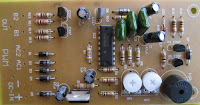
This inverter uses PWM (Pulse Width Modulator) with type IC SG3524. IC serves as a oscillator 50Hz, as a regulator of the desired output voltage. Input power ranging from 250W up to 5000W output and has. Following a series INVERTER 5000W with PWM (Pulse Width Modulator).
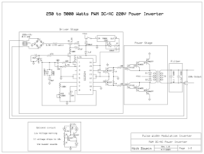 |
| Schematic Inverter 5000W with PWM (Pulse Width Modulator) |
 |
| Layout PCB Inverter 5000W with PWM (Pulse Width Modulator) |
below is the output power settings that can be issued by this inverter:
DC voltage and Transformer "T2" winding recommendation:
Winding Power Supply
12VDC 750W P: 24V "12-0-12" / S: 220V
1500W 24VDC P: 48V "24-0-24" / S: 220V
2250w 36VDC P: 72V "36-0-36" / S: 220V
3000w 48VDC P: 96V "48-0-48" / S: 220V
3750w 60VDC P: 120V "60-0-60" / S: 220V
4500w 72VDC P: 144V "72-0-72" / S: 220V
5250w 84VDC P: 168V "84-0-84" / S: 220V
Transformer used is the transformer CT
R1 serves to regulate the voltage to 220v inverter
R2 serves to regulate the inverter output frequency of 50 or 60 Hz (as appropriate)

Tuesday, October 15, 2013
20W amplifier schematic with mute
This is a series of audio amplifier using ic and equipped with a mute switch. This circuit using ic and has 20W output impedance 4 ohms. Scheme and a list of components can be seen below.

Part List :
Resistor
R1 = 3.3K
R2 = 39R
R3 = 39R
R4 = 3.3K
R5 = 3R
R6 = 3R
Capacitor
C1 = 1uF
C2 = 1uF
C3 = 10uF
C4 = 100uF
C5 = 100uF
C6 = 220uF
C7 = 0.1uF
C8 = 0.1uF
IC
IC = ULN3793W
Saturday, October 12, 2013
Basic Automatic Day Night Lamp with LDR
Automatic Day-Night Lamp wit LDR

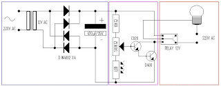
Maybe its a lot who know how to work this one series, but I wanted to share back to the beginner on this. In the existing lighting circuit automatic lights that use components LDR (Light Dependence Resistor).
The workings of LDR LDR is exposed to light if the layer of the resistance was weakened likewise if there is no light at all resistance enlarged. here could make friends like that, because its components are a little easy but we will use the 220V AC voltage of course you must be very careful. Rather than actually being burnt. The author asks to be careful for the beginner course.
Continue[...]
Maybe its a lot who know how to work this one series, but I wanted to share back to the beginner on this. In the existing lighting circuit automatic lights that use components LDR (Light Dependence Resistor).
The workings of LDR LDR is exposed to light if the layer of the resistance was weakened likewise if there is no light at all resistance enlarged. here could make friends like that, because its components are a little easy but we will use the 220V AC voltage of course you must be very careful. Rather than actually being burnt. The author asks to be careful for the beginner course.
 |
| Schematic LDR |
LDR components can be interconnected with a cable, so tools stay in the house but LDR is outside the home. It is recommended using qualified Relay no1 to avoid fire, because the relays are cheap to produce heat. Relay that cheap is not in use for high voltage. Travonya use the cheap, because this circuit does not require large currents. The function of Potensio 500KΩ to regulate Q1 & Q2 is on, if both the active transistor relay also participate actively.
Friday, October 11, 2013
Circuit High Voltage Generator with HEX FET
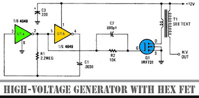
The schematic diagram below show a circuit of high voltage generator. This circuit uses a 4049 hex inverter as an oscillator, and you can use ignition transformer from automotive engine. A fly-back transformer is possibly usable too. The 4049 will drive the IRF731 HEX FET. The Q1 must be heatsinked. Here is the schematic diagram of the circuit:
Thursday, October 10, 2013
Amplifier Output Delay with Relay
This is a minimal circuit which I built to individual of my audio amplifier projects to control the presenter output relay. The end of this circuit is to control the relay which turns on the speaker output relay within the audio amplifier. The impression of the circuit is time lag around 5 seconds ofter the power up until the speakers are switched to the amplifier output to circumvent grating “pound” sound from the speakers. an added appear of this circuit is so as to is disconnects the orator just now once the power within the amplifier is finish inedible, so avoiding every now and then nasty sounds as soon as you trip the equipments inedible.
 |
| Amplifier Output Delay with Relay Circuit Diagram |
Followed by power is functional to the power input of the circuit, the categorical stage of AC voltage charges C1. Then C2 starts to charge little by little through R1. while the voltage in C2 rises, the emitter output voltage of Q1 rises concurrently with voltage on C2. as the output voltage of Q2 is anticyclone an adequate amount of (typically around 16..20V) the relay goes to on state and the relay witches associate the speakers to the amplifier output. It takes typically around 5 seconds in the same way as power up until the relay starts to conduct (next to absolute epoch depends on the size of C2, relay voltage and circuit input voltage). as the power is switched rotten, C1 force not tied up it’s energy quite quickly. and C2 will transpire charged quite quickly through R2. into excluding than 0.5 seconds the speakers are disconnected from the amplifier output.
Saturday, October 5, 2013
Fire alarm with light sensor
Fire alarm can be made with a light sensor (LDR) as in the article with the title of Fire Alarm with this LDR sensor. Principles of fire detection Fire Alarm with LDR sensor is to detect the presence of smoke through the LDR. LDR in the series Fire Alarm does not stand alone in detecting a fire, but the LDR in the pair with the light shining on the LDR.
Hence, in the detected smoke from the fire then the intensity of light received by the LDR LDR decreases and eventually trigger an alarm system on a series of Fire Alarm with this LDR sensor. Part 2 that in the series of Fire Alarm with Sensor LDR are some of the sensors, tone generator, audio power.
Image Series Fire Alarm with Sensor LDR

Function Section of the Fire Alarm with Sensor LDR
Part of LDR and light sensor facing to fire smoke detection
Part trigger using transistors and regulators as a trigger tone generator 7805
Tone generator section with IC UM66
Power audio section uses an audio power IC TDA 2002 which is equipped with voleme control (R3)
Subscribe to:
Posts (Atom)