Showing posts with label sensor. Show all posts

Thursday, October 23, 2014

Line Following Robot Sensor

This Line Following Robot sensor or surface scanner for robots is a very simple, stamp-sized, short range (5-10mm) Infrared proximity detector wired around a standard reflective opto-sensor CNY70(IC1). In some disciplines, a line following robot or an electronic toy vehicle go along a predrawn black line on a white surface. In such devices, a surface scanner, pointed at the surface is used to align the right track.

IC1 contains an infrared LED and a phototransistor. The LED emit invisible infrared light on the track and the phototransistor works as a receiver. Usually, black colored surface reflects less light than white surface and more current will flow through the phototransistor when it is above a white surface. When a reflection is detected (IR light falls on the phototransistor) a current flows through R2 to ground which generates a voltage drop at the base of T1 to make it conduct. As a result, transistor T2 start conducting and the visual indicator LED(D1) lights up. Capacitor C2 works as a mini buffer.

Line Follower Robot Scanner Schematic

Circuit Project: Line Following Robot Sensor

After construction and installation, the scanner needs to be calibrated. Initially set P1 to its mechanical centre position and place the robot above the white portion of the track. Now slowly turn P1 to get a good response from D1. After this, fine tune P1 to reduce false detection caused by external light sources. Also ensure that the LED remains in off condition when the sensor module is on the blackarea. Repeat the process until the correct calibration is achieved.

The red color LED (D1) is only a visual indicator. You can add a suitable (5V) reed relay in parallel with D1-R4 wiring after suitable alterations to brake/stop/redirect the robot. Similarly, the High to low (H-L) transition at the collector of T2 can be used as a signal to control the logic blocks of the robot. Resistor R1 determines the operating current of the IRLED inside IC1. The sensing ability largely depends on the reflective properties of the markings on the track and the strength of the light output from IC1.
Continue[...]

Friday, October 17, 2014

Fog Lamp Sensor Circuit Diagram

For several years now, a rear fog lamp has been mandatory for trailers and caravans in order to improve visibility under foggy conditions.
Circuit diagram :
Fog Lamp Sensor-Circuit Diagram
Fog Lamp Sensor Circuit Diagram
When this fog lamp is switched on, the fog lamp of the pulling vehicle must be switched off to avoid irritating reflections. For this purpose, a mechanical switch is now built into the 13-way female connector in order to switch off the fog lamp of the pulling vehicle and switch on the fog lamp of the trailer or caravan. For anyone who uses a 7-way connector, this switching can also be implemented electronically with the aid of the circuit illustrated here.
Here a type P521 optocoupler detects whether the fog lamp of the caravan or trailer is connected. If the fog lamp is switched on in the car, a current flows through the caravan fog lamp via diodes D1 and D2. This causes the LED in the optocoupler to light up, with the result that the phototransistor conducts and energises the relay via transistor T1. The relay switches off the fog lamp of the car.
For anyone who’s not all thumbs, this small circuit can easily be built on a small piece of perforated circuit board and then fitted somewhere close to the rear lamp fitting of the pulling vehicle.
Continue[...]

Wednesday, December 25, 2013

Battery Charger with Temeperature Sensor

Battery Charger with Temeperature Sensor


Battery with a LM35 temperature sensor on the charger used to monitor the battery temperature is in charge. Battery temperature sensor is needed because the battery temperature will rise at the time in charge. Battery temperature sensor LM35 temperature sensor has high accuracy in monitoring the battery temperature, it is because the temperature sensor LM35 is a temperature sensor that can convert temperature changes into voltage changes linearly.


At the time of the charge a battery will experience changes in temperature, where the battery temperature will begin to rise when the battery began to fill. To avoid over heat the battery, the battery temperature sensor LM35 temperature sensor is required to terminate the battery charging current to avoid overheating.

battery charger schematic with LM35
Battery charger with temperature sensor schematic

On the battery charger circuit temperature sensor with temperature sensor 35 lm above the R1 is used for setting the maximum value of the desired temperature. Therefore, when the temperature was in-charge the battery begins to rise and reach temperatures setup then this series will break the current battery charge.
Continue[...]

Saturday, December 7, 2013

9 Channels Sensor Switch

This sensor switch circuit diagram is designed using CMOS components. This sensor switch circuit has nine channels and consist of only three integrated circuits and some resistors. Due to high input impedance, 74HC147 allows to use of 4.7 M resistors to create a logic level "high" to sensor inputs. When one sensor is touched, the resulting low resistance to ground circuit causes IC1 to read a logical level L.

9 Channels Sensor Switch Circuit Diagram
If several sensors are touched simultaneously, priority encoder delivers 4-bit code corresponding to the sensor with the highest number.
Continue[...]

Sunday, November 17, 2013

Electronic Components As Light Sensor

Electronic Components As Light Sensor

Electronic components are included in the category of light sensors is LDR, Photo Transistor, Photo Diode, Infrared Receiver. The function of the electronic component is to detect the intensity of light received by the component. The light sensor is often used in electronic equipment such as on television, light a light switch, light intensity measuring instrument.

Electronic Components As Light Sensor
Electronic Components As Light Sensor 
Continue[...]

Thursday, November 14, 2013

Basic LM35 temperature sensor circuit

 This is basic of workmaship LM35 temperatur sensor, whish is taken from the LM35 spending and boosted again by the amplifier op-amp. High output if the sensor is received by ic LM35 high temperature . You can use the output as driver relay, fan , or other. And if yo want to see modifications LM35 temperature sensor see here.


Continue[...]

Thursday, October 24, 2013

Heat Sensor Fire Detector Pyroelectric

Pyroelectric
Detect the presence of fire in the world of electronics can be done by detecting changes in temperature, the presence of UV ultraviolet rays and infrared light IR. Heat Sensor pyroelectric detectors Eltec E442-3 is a heat sensor (fire) that detect the presence of infrared ray IR, and therefore often called IR-EYE.

These sensors form of Lithium Tantalate pyroelectric parallel opposed dual element high gain detector with integrated analog signal processing. These sensors can detect heat changes from -40 to +70 degrees Celsius without change siginfikan of noise and sensitivity.

To use heat sensor pyroelectric detectors Eltec E442-3, it can take a kind of cone is covered with a fresnel lens to focus the direction of the infrared ray IR. Heat sensors then pyroelectric detectors Eltec E442-3 inserted into the cone is then connected to the microcontroller. Analog output value signals which when detects heat, the sensor will cause a drastic change in output voltage.
Continue[...]

Saturday, October 5, 2013

Fire alarm with light sensor

Fire alarm can be made with a light sensor (LDR) as in the article with the title of Fire Alarm with this LDR sensor. Principles of fire detection Fire Alarm with LDR sensor is to detect the presence of smoke through the LDR. LDR in the series Fire Alarm does not stand alone in detecting a fire, but the LDR in the pair with the light shining on the LDR.


Hence, in the detected smoke from the fire then the intensity of light received by the LDR LDR decreases and eventually trigger an alarm system on a series of Fire Alarm with this LDR sensor. Part 2 that in the series of Fire Alarm with Sensor LDR are some of the sensors, tone generator, audio power.


Image Series Fire Alarm with Sensor LDR


Function Section of the Fire Alarm with Sensor LDR
Part of LDR and light sensor facing to fire smoke detection
Part trigger using transistors and regulators as a trigger tone generator 7805
Tone generator section with IC UM66
Power audio section uses an audio power IC TDA 2002 which is equipped with voleme control (R3)
Continue[...]

Sunday, September 22, 2013

Gas SENSOR MODULE


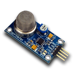
The SEN-1327 LPG chatter Sensor Module is designed to enable LPG detection interface to Microcontroller devoid of ADC Channels. It allows to determine while a set LPG chatter level has been reached otherwise exceeded. Interfacing with the sensor module is made through a 4-pin SIP title and requires lone I/O pin from the host microcontroller.

The onboard microcontroller provide preliminary heating interval bearing in mind powerup and therefore starts to meassure LPG sensor output.If it found the LPG contents exceeding setted estimate, it self-control tell the Host controller by pulling the Output Pin to elevated and Starts to blink a onboard status LED. The sensor module is for the most part intended to provide a revenue of comparing LPG sources and being able to prearranged an alarm limit whilst the source becomes unnecessary.
SEN1327 pins configuration and photo

Gas SENSOR MODULE

SEN-1327 module skin texture
  • Uses the MQ-6 LPG gab Sensor
  • undemanding SIP interface
  • Compatible with largely microcontrollers
  • Onboard Status and Power LED
  • Onboard Pot representing threshold setting
  • On board microcontroller

Continue[...]