Showing posts with label low. Show all posts
Showing posts with label low. Show all posts
Friday, October 17, 2014
build a Low Cost Stereo Level Indicator
Usually, Low-Cost Stereo Level Indicator home stereo power amplifiers don’t have output level indicators. An output power level indicator can be added to each channel of these stereo power amplifiers. As low levels of the output power are not disturbing and damaging to the people, there is no need to add a preamplifier and low-level detector before IC LM3915. But you should know when the output power becomes considerably high.
Here we present a very simple, low-cost stereo-level indicator circuit for home power amplifiers with power rating of around 0.5W. The circuit is built around two LM3915 dot/bar display driver ICs (IC1 and IC2). LM3915 senses analogue voltage levels to drive ten LEDs, providing a logarithmic 3dB/step analogue display.
Stereo Level Indicator Circuit Diagram
Here we present a very simple, low-cost stereo-level indicator circuit for home power amplifiers with power rating of around 0.5W. The circuit is built around two LM3915 dot/bar display driver ICs (IC1 and IC2). LM3915 senses analogue voltage levels to drive ten LEDs, providing a logarithmic 3dB/step analogue display.
Stereo Level Indicator Circuit Diagram

The voltage levels below 1V are not important because these correspond to a low level of the audio signal. Similarly, input voltage levels above 30V correspond to too high levels of the output power, which are not applicable for home power amplifiers. So the voltage levels of our interest are 1V to 30V, which can be handled directly with LM3915. LM3915 needs no protection against ±35V inputs, which simplifies the circuit.
Most audio power amplifiers can drive 2-ohm to around 32-ohm loads. A load of several kilo-ohms will not change the conditions for the amplifier. CON1 is the input connector and CON2 output connector for the loudspeaker or headphone. Each channel has its own LM3915 and ten LEDs to indicate the power level. To indicate the different audio levels, select LEDs of three colours as per your liking. For example, you can have five green LEDs, three yellow LEDs and two red LEDs.
If appropriate signal generators and measuring equipment are not available, the level indicator can be calibrated based on personal observations. For example, the audio signal should be in the green LEDs zone when the signal is strong enough but not irritating, in the yellow zone when it is disturbing or starting to get distorted, and in the red zone when it is heavily distorted or too strong to listen to in the room.
Calibration can be done with the help of potentiometers VR1 and VR2, which are optional. Switches S1 and S2 let you select between two modes of LM3915 operation—the bar mode and the dot mode. These too can be removed or replaced with jumpers, if not required. When the switches are removed, leave pins 9 of IC1 and IC2 open.
The circuit works off regulated 12V. You can also power it through a 12V rechargeable battery.
Assemble the circuit on a general-purpose PCB and enclose in a suitable cabinet. Fix all the LEDs in two rows on the front side of the cabinet. Also affix the two terminals for input and output on rear side of the cabinet. link
Most audio power amplifiers can drive 2-ohm to around 32-ohm loads. A load of several kilo-ohms will not change the conditions for the amplifier. CON1 is the input connector and CON2 output connector for the loudspeaker or headphone. Each channel has its own LM3915 and ten LEDs to indicate the power level. To indicate the different audio levels, select LEDs of three colours as per your liking. For example, you can have five green LEDs, three yellow LEDs and two red LEDs.
If appropriate signal generators and measuring equipment are not available, the level indicator can be calibrated based on personal observations. For example, the audio signal should be in the green LEDs zone when the signal is strong enough but not irritating, in the yellow zone when it is disturbing or starting to get distorted, and in the red zone when it is heavily distorted or too strong to listen to in the room.
Calibration can be done with the help of potentiometers VR1 and VR2, which are optional. Switches S1 and S2 let you select between two modes of LM3915 operation—the bar mode and the dot mode. These too can be removed or replaced with jumpers, if not required. When the switches are removed, leave pins 9 of IC1 and IC2 open.
The circuit works off regulated 12V. You can also power it through a 12V rechargeable battery.
Assemble the circuit on a general-purpose PCB and enclose in a suitable cabinet. Fix all the LEDs in two rows on the front side of the cabinet. Also affix the two terminals for input and output on rear side of the cabinet. link

Sunday, December 15, 2013
Low Power Transceiver Using by ADF7242
This low power transceiver circuit project is designed using the ADF7242 fully integrated low-cost, short-range, low power transceiver designed for operation in the global 2.4 GHz ISM band.The receive path of the ADF7242 low power transceiver circuit is based on a zero-IF architecture enabling high blocking and selectivity performance. The transmit path is based on a direct closed loop VCO modulation scheme. The ADF7242 has a low consumption power that make it suitable for battery powered systems.
Low Power Transceiver Circuit diagram

The ADF7242 supports IEEE 802.15.4 compliant DSSS-OQPSK modulation with a bitrate of 250 kbps and also supports FSK and GFSK modulation with bitrates from 62.5 kbps to 2 Mbps.ADF7242 fully supports arbitrary data rates only for FSK mode of operation. The ADF7242 also has a built in battery monitor features that has a very low power consumption and may be used in parallel with any mode of operation, except SLEEP state. The battery monitor generates a battery alert interrupt for the MCU when the battery voltage drops below the programmed threshold voltage.
Low Power Transceiver Circuit diagram
The ADF7242 supports IEEE 802.15.4 compliant DSSS-OQPSK modulation with a bitrate of 250 kbps and also supports FSK and GFSK modulation with bitrates from 62.5 kbps to 2 Mbps.ADF7242 fully supports arbitrary data rates only for FSK mode of operation. The ADF7242 also has a built in battery monitor features that has a very low power consumption and may be used in parallel with any mode of operation, except SLEEP state. The battery monitor generates a battery alert interrupt for the MCU when the battery voltage drops below the programmed threshold voltage.
Wednesday, November 6, 2013
Minimal low supply rail detection
At this point’s a minimal low supply rail detection circuit with the purpose of expenditure peanuts and takes a short time ago 20 minutes or else so to become. Its power consumption is quite low, so it may perhaps definitely survive built into battery-powered campaign. as an alternative of using an op amp, the circuit is built around three low-cost transistors (Q1-Q3). Diodes D1-D3 form a 1.8V voltage reference (Vref) used for the emitter of Q1. If the voltage across the voltage wall formed by R1 and VR1 is a reduced amount of than this, Q1 turns on and food Q2 with foundation bias current.

This turns on Q3 here proportion to this bias current which subsequently drives LED1. The brightness of the LED gives an indication of the severity of the low voltage condition. The brighter the LED, the minor the supply voltage. Trimpot VR1 is adjusted so to facilitate LED1 really comes on by the desired low-voltage promontory. The current consumption is typically take away than 2mA at what time LED1 is rotten. in conclusion, the price exposed in support of RLED is right for 6-12V surgery. For other voltages, RLED can ensue calculated using the formula RLED = (Vcc - 1.8)/0.01 (this equates to a current of with reference to 10mA).
Wednesday, October 2, 2013
Ultra Low Power LCD Indicator
This circuit serves as an ultra-low power replacement for multiple LED on-off indicators. It also has the advantage of being easy to read in full daylight. With the parts shown, it is possible to display four bits of information.

The display that I used has three digits and 2 decimal points for a total of 23 segments. Different groupings of segments can be used for the four indicators. I chose to use three squares (shown) and the three lower segments together (not shown) for the four indicators. Many other combinations could be used, one possibility would be to hard-wire numbers or letters out of each of the digits. Other LCD displays could also be used for different effects.
Circuit Diagram

A part that doesnt exist as far as I know, but should, is a single pixel LCD indicator (2 wire). An LCD manufacturer could probably make a lot of money with such a part. If such a thing exists, Id love to hear about it.
Specifications:
Operating Voltage: 3-15V (5V Nominal) DC
Operating Current: 250 microamps to 1 milliamp (400 microamps at 5V)
Operating Frequency: approximately 60 Hz
Theory:
The 7555 IC (CMOS 555 timer) generates a square wave clock signal at approximately 60 hz. This signal is sent to the LCD backplane and the inputs of the four CMOS 4070 XOR gates. If the other input (ind*) of an XOR gate is low, the gates output is a square wave that is in phase with the clock signal. If the ind* input is high, the gates output is out of phase with the clock.
Sending a signal to an LCD segment that is in phase with the backplane signal causes the display to stay blank. Sending an out of phase signal to the LCD segment causes an AC waveform to be applied to the segment which turns it black. Multiple segments are wired in parallel to generate the desired display patterns. The LCD segments require a tiny amount of current to operate, the CMOS gates also take very little power, hence the efficient nature of the circuit. It is necessary to tie the unused segments to the LCD backplane, otherwise they may partially turn on.
If more dislay bits are needed, additional XOR gates can be connected in the same manner. Up to 23 XOR gates could be used to drive the entire display, but a microprocessor and driver software would probably be easier to put together. By generating all of the signals with a microprocessor, all of the driving circuitry can be eliminated.
Other logic families could be used to make this circuit, it should work with a standard 555 timer chip and a 74LS86 XOR gate (different pinout), for example.
Some LCDs may not operate at very cold temperatures, an engineer at Lumex said that their components will work from -30C to +75C.
Construction:
The circuit was built on a standard prototyping plug board. All of the parts can be purchased for under ten dollars.
Use:
The four inputs of the CMOS 4070 IC can connect to outputs on a microprocessor, or any other logic output that needs monitoring. The supply voltage of this circuit should be the same as the driving logics supply voltage.
Parts:
1X Lumex LCD-S301C31TR 3 digit LCD display (from Digi-Key), or equivalent
1X CMOS 4070 quad XOR Gate, a CMOS 4030 should also work.
1X 7555 CMOS 555 timer chip
2X 100nF capacitor
1X 100uF 25V electrolytic capacitor
1X 10K 1/4W resistor
1X 100K 1/4W resistor
The display that I used has three digits and 2 decimal points for a total of 23 segments. Different groupings of segments can be used for the four indicators. I chose to use three squares (shown) and the three lower segments together (not shown) for the four indicators. Many other combinations could be used, one possibility would be to hard-wire numbers or letters out of each of the digits. Other LCD displays could also be used for different effects.
Circuit Diagram
A part that doesnt exist as far as I know, but should, is a single pixel LCD indicator (2 wire). An LCD manufacturer could probably make a lot of money with such a part. If such a thing exists, Id love to hear about it.
Specifications:
Operating Voltage: 3-15V (5V Nominal) DC
Operating Current: 250 microamps to 1 milliamp (400 microamps at 5V)
Operating Frequency: approximately 60 Hz
Theory:
The 7555 IC (CMOS 555 timer) generates a square wave clock signal at approximately 60 hz. This signal is sent to the LCD backplane and the inputs of the four CMOS 4070 XOR gates. If the other input (ind*) of an XOR gate is low, the gates output is a square wave that is in phase with the clock signal. If the ind* input is high, the gates output is out of phase with the clock.
Sending a signal to an LCD segment that is in phase with the backplane signal causes the display to stay blank. Sending an out of phase signal to the LCD segment causes an AC waveform to be applied to the segment which turns it black. Multiple segments are wired in parallel to generate the desired display patterns. The LCD segments require a tiny amount of current to operate, the CMOS gates also take very little power, hence the efficient nature of the circuit. It is necessary to tie the unused segments to the LCD backplane, otherwise they may partially turn on.
If more dislay bits are needed, additional XOR gates can be connected in the same manner. Up to 23 XOR gates could be used to drive the entire display, but a microprocessor and driver software would probably be easier to put together. By generating all of the signals with a microprocessor, all of the driving circuitry can be eliminated.
Other logic families could be used to make this circuit, it should work with a standard 555 timer chip and a 74LS86 XOR gate (different pinout), for example.
Some LCDs may not operate at very cold temperatures, an engineer at Lumex said that their components will work from -30C to +75C.
Construction:
The circuit was built on a standard prototyping plug board. All of the parts can be purchased for under ten dollars.
Use:
The four inputs of the CMOS 4070 IC can connect to outputs on a microprocessor, or any other logic output that needs monitoring. The supply voltage of this circuit should be the same as the driving logics supply voltage.
Parts:
1X Lumex LCD-S301C31TR 3 digit LCD display (from Digi-Key), or equivalent
1X CMOS 4070 quad XOR Gate, a CMOS 4030 should also work.
1X 7555 CMOS 555 timer chip
2X 100nF capacitor
1X 100uF 25V electrolytic capacitor
1X 10K 1/4W resistor
1X 100K 1/4W resistor
Tuesday, September 24, 2013
Basic Low Pass Filter

Low pass filter is a low-pass filter with low frequency signals but attenuates (reduces the amplitude of) signals with frequencies higher than cutoff frequency. The actual amount of damping for each frequency varies from filter to Filtering.
Sometimes called-high-cut filter, or treble cut filter when used in audio applications. Low-low pass filter is the opposite of the band-pass filter.
Sometimes called-high-cut filter, or treble cut filter when used in audio applications. Low-low pass filter is the opposite of the band-pass filter.
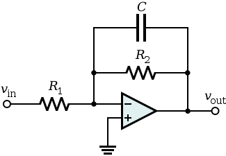 |
| Low Pass Filter Basic Circuit |
The concept of low-pass filter exists in many forms, including electronic circuits (like a hiss filter used in audio), digital algorithms for smoothing data sets, acoustic barriers, blurring the image, and so forth.
Subscribe to:
Posts (Atom)