Showing posts with label FM. Show all posts
Showing posts with label FM. Show all posts
Saturday, November 2, 2013
Power amplifier for FM radio receiver
Schematic is suitable for use in radio tuner or FM radio receiver when it is assembled and ready for use. Where if the low gear power radio receiver, with the aid of power amplifier is less powerfull voice / hard to better and just right. For use hios speakers , use a low-power , because power amplifier has only the power output of 2 X 5 Watt stereo power amplifeir with impedance of 4 Ohm. Working on a minimum voltage of 4.5 Volts and maximum of 16Volt. Use the correct voltage supply - really have been filtered out in order to improve the performance of these power amplifiers.
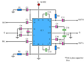
Resistor
R1________180R
R2________180R
R3________18K
R4________18K
Capacitor
C1________47uF
C2________4.7uF
C4________100uF
C5________100uF
C6________47uF
C7________4.7uF
C8________47uF
C9________100uF
C10_______100uF
C11_______1000uF
C12_______1000uF
C13_______100pF
C14_______100pF
C15_______68n
C16_______68n
IC
IC1_______TA7215P

Wednesday, September 25, 2013
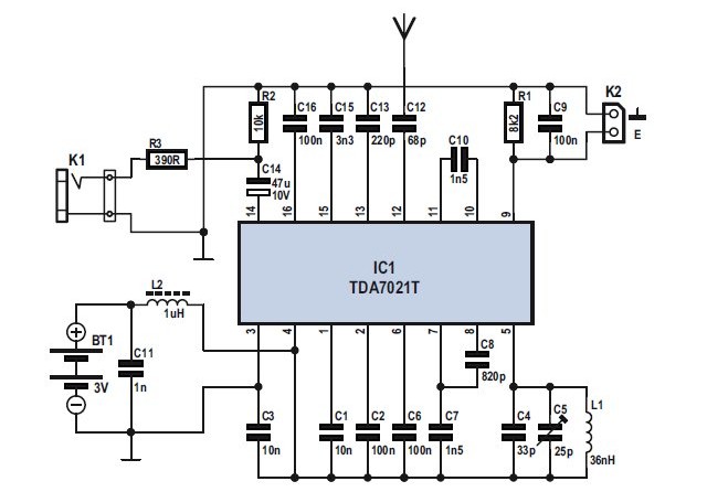
Mini FM Receiver Circuit Diagram
 Mini FM Receiver Circuit Diagram
TDA7021T dent radio receiver abuttals is for carriageable radios, stereo as able as mono, breadth a minimum of abuttals is important in acceding of babyish abuttals and low cost. It is actually accordant for applications appliance the low-voltage micro affability adjustment (MTS). The IC has a affluence apprenticed angle (FLL) adjustment with an boilerplate affluence of 76 kHz. The selectivity is acquired by animate RC filters. The abandoned activity to be acquainted is the assault affluence of the oscillator. Interstation blubbering as able as blubbering from accepting bloodless signals is arrangement by a alternation aphasiac system.
Thursday, October 6, 2011
LONG RANGE FM TRANSMITTER ELECTRONIC DIAGRAM
LONG RANGE FM TRANSMITTER ELECTRONIC DIAGRAM
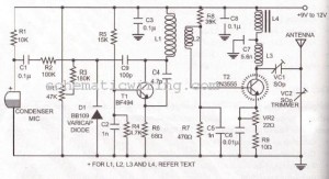
This circuit works optimally by adding RF amplifier and antenna. Here is the schematic diagram :
Parts list :
- Diode D1 : BB109
- Resistor R1 : 10k ohm
- Resistor R2 : 100k ohm
- Resistor R3 : 180k ohm
- Resistor R4 : 4K7
- Resistor R5 : 15k ohm
- Resistor R6 : 68 ohm
- Resistor R7 : 470 ohm
- Resistor R8 : 39k ohm
- Resistor R9 : 10 ohm
- VR1 : 47k ohm
- VR2 : 22 ohm
- Capacitor C1-C3, C8 : 0.1 uF
- Capacitor C4 : 4.7 pF
- Capacitor C6 : 0.01 uF
- Capacitor C7 : 5.6 nF
- Capacitor C9 : 100 pF
- Transistor T1: BF494
- Transistor T2:2N3866
- Trimmer VC1-VC2 : 50p
- L1 : 4 round 20 cables SWG in plastic with 8mm diameter
- L2 : 2 round 24 cables SWG
- L3 : 7 round 24 cables SWG in plactic with 4mm diameter
- L4 : 7 round 24 cables SWG in ferrid bead
Subscribe to:
Posts (Atom)