Showing posts with label TRANSMITTER. Show all posts
Showing posts with label TRANSMITTER. Show all posts
Friday, October 17, 2014
Small Circuit Multiband Radio Transmitter CW
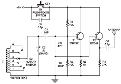
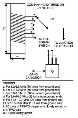
This is a Small Circuit Multiband Radio -Transmitter CW for who wants to learn more about radiofrequency, mainly operating principle from radios transceivers multiband, That circuit consists of a frequency oscillator RF, which is the main component us transmitters and radio receivers.
He oscillates for high frequency, he is called variable frequency oscillator or VFO, their frequency may vary of 5.2 MHz to 15 MHz, depending the coil chosen and signal can be received in the band shortwave by any receiver radio.In S1 is used a switch type bell, but can-if use a handler CW, these used by radio amateurs. How antenna should-if use a the type dipole from 1/4 wave.

Monday, October 14, 2013
Transmitter and Receiver AM Superheterodyne
TRANSMITTER AND RECEIVER AM SUPERHETERODYNE
Distribution of information from one place to another can be done with a wide - variety of ways. As one way to distribute information in a radio communications technique, was made with modulated AM transmitter rise. The term superheterodyne stands for supersonic heterodyne, which can be interpreted as the generation of mixed frequencies above the hearing.
 |
| Transmitter |
 |
| Receiver |
-AM-Transmitter
AM transmitter is a transmitter that utilizes analog modulation techniques are AM (Amplitude Modulation), to transmit information signals. The source carrier is driven by a crystal oscillator at the carrier frequency or multiples below. The amount of output frequency can be adjusted by changing the value of L and C. Cultivated constant frequency emitted wave output generated for the better. This was followed by a buffer amplifier tuned. With the buffer labored to frequencies generated by the oscillator constant. Signal information entered on this circuit to be mixed with a carrier signal. At the transmitter, there are a series of modulators, which generally is a class C amplifier Class C amplifier is actually resulted in the emergence of unexpected flaw in the envelope modulation signal containing information. The output of RF amplifier is transmitted via an antenna.
Superheterodyne-AM-Receiver
AM receiver functions to receive signals modulated AM and do the demodulation of the signals. The signal was first received by the antenna, then the selection signals are separated is then amplified to a level that can separate the information signal from the signal (carrier) at the time of the AM demodulator or detector AM. Recipients an old-fashioned AM
used for receiving amplitude modulated signals typically use the principle of a tuned radio frequency or TRF. Recipients of this kind have poor selectivity adjacent signals, especially when required to tune in scope - a wide frequency range.
Therefore now superheterodyne receiver was developed to improve the selectivity of the channel adjacent fatherly (adjacent channel selectivity) of this by placing the bulk of the frequency selectivity at the level - the level of intermediate frequency (IF) after the first frequency conversion much easier fatherly get this selectivity in the IF, because stay tuned to the IF circuit and does not change even if the selected stations - different stations. Superheterodyne principle occurs when when two sinusoidal signals with different frequencies are mixed, so that they multiply or add to each other and the output signal will contain components - the component signal at a frequency which is the sum, difference and of the two original frequencies. There is also a mixture of harmonics of this signal, but if the second fundamental frequency is selected with the heart - this heart does not interfere with each other (interference).
The first level of a tuned RF functions to improve the ratio S / N. This level also provides a little perbaiakn RF selectivity and a decrease in back of the oscillator beam. Then tune the RF output is fed to the input signal from an oscillator circuit where there penyampur generation with tuning capacitance, and a third tuning capacitor (tuning capacitor) together (ganged) mechanically on a common axis and button settings. Penyampur oscillator and can be a separate circuit or it can also be combined as in the series penyampur autodyne. Next penyampur fed into two IF amplifier tuning, which remains tuned and has sufficient selectivity to reject signals from the channel boundaries. The output of the IF amplifier is inserted into the detector, where the audio signal generated back or in demodulation. The detector also provides a signal for automatic acquisition settings (Automatic Gain Control).
AGC signal applied to one or several of IF and RF amplifiers. Audio output, transmitted through a volume control to the audio amplifier, which usually consists of one low-level voltage amplifier followed by a
power amplifier and finally connected to a loudspeaker.
Thursday, October 6, 2011
LONG RANGE FM TRANSMITTER ELECTRONIC DIAGRAM
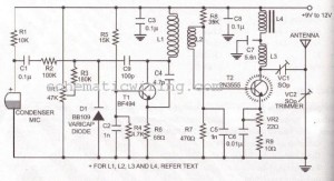
LONG RANGE FM TRANSMITTER ELECTRONIC DIAGRAM
This circuit works optimally by adding RF amplifier and antenna. Here is the schematic diagram :
Parts list :
- Diode D1 : BB109
- Resistor R1 : 10k ohm
- Resistor R2 : 100k ohm
- Resistor R3 : 180k ohm
- Resistor R4 : 4K7
- Resistor R5 : 15k ohm
- Resistor R6 : 68 ohm
- Resistor R7 : 470 ohm
- Resistor R8 : 39k ohm
- Resistor R9 : 10 ohm
- VR1 : 47k ohm
- VR2 : 22 ohm
- Capacitor C1-C3, C8 : 0.1 uF
- Capacitor C4 : 4.7 pF
- Capacitor C6 : 0.01 uF
- Capacitor C7 : 5.6 nF
- Capacitor C9 : 100 pF
- Transistor T1: BF494
- Transistor T2:2N3866
- Trimmer VC1-VC2 : 50p
- L1 : 4 round 20 cables SWG in plastic with 8mm diameter
- L2 : 2 round 24 cables SWG
- L3 : 7 round 24 cables SWG in plactic with 4mm diameter
- L4 : 7 round 24 cables SWG in ferrid bead
Subscribe to:
Posts (Atom)