Tuesday, January 14, 2014
SMS Remote controller circuit
Series AVR ATTiny To SMS Remote Controller
 |
| SMS Remote controller circuit Click to view larger. |
AVR circuit this part ATTiny To SMS Remote Controller
- 4 Relay for ON / OFF electronic devices
- 8 input lines for reading in a normal switching
- LED indicators signal operator
- SMS command with password, so only the owner can operate
Monday, January 13, 2014
Schematic Audio Amplifier with IC AN5260

Sunday, January 12, 2014
1000W Mosfet Power Inverter
 |
| 1000W Mosfet Power Inverter |
Saturday, January 11, 2014
Control Relay Circuit with 9 Second
Friday, January 10, 2014
Audio Stereo Channel Selector Circuit
 Audio Stereo Channel Selector Circuit
This circuit has accouterment for abutting stereo outputs from four altered sources/channels as inputs and alone one of them is selected/connected to the achievement at any one time.
When ability accumulation is angry ‘on’, approach A (AR and AL) is selected. If no audio is present in approach A, the ambit waits for some time and again selects the abutting approach (channel B). This chase operation continues until it detects audio arresting in one of the channels. The inter-channel adjournment or adjournment time can be adapted with the advice of preset VR1. If still best time is needed, one may alter capacitor C1 with a capacitor of college value.
Suppose approach A is affiliated to a band recorder and approach B is affiliated to a radio receiver. If initially approach A is selected, the audio from the band recorder will be present at the output. After the band is played completely, or if there is acceptable abeyance amid after recordings, the ambit automatically switches over to the achievement from the radio receiver. To manually skip over from one (selected) alive approach to addition (non-selected) alive channel, artlessly advance the skip about-face (S1) briefly already or more, until the adapted approach ascribe gets selected. The called approach (A, B, C, or D) is adumbrated by the aglow of agnate LED (LED11, LED12, LED13, or LED14 respectively).
IC CD4066 contains four alternation switches. These switches are affiliated to four abstracted channels. For stereo operation, two agnate CD4066 ICs are acclimated as apparent in the circuit. These alternation switches are controlled by IC CD4017 outputs. CD4017 is a 10-bit arena adverse IC. Since alone one of its outputs is aerial at any instant, alone one about-face will be bankrupt at a time. IC CD4017 is configured as a 4-bit arena adverse by abutting the fifth achievement Q4 (pin 10) to the displace pin. Capacitor C5 in affiliation with resistor R6 forms a power-on-reset ambit for IC2, so that on antecedent switching ‘on’ of the ability supply, achievement Q0 (pin 3) is consistently ‘high’. The alarm arresting to CD4017 is provided by IC1 (NE555) which acts as an astable multivibrator back transistor T1 is in cut- off state.
IC5 (KA2281) is acclimated actuality for not alone advertence the audio levels of the called stereo channel, but additionally for advanced biasing transistor T1. As anon as a specific beginning audio akin is detected in a called channel, pin 7 and/or pin 10 of IC5 goes ‘low’. This low akin is accompanying to the abject of transistor T1, through diode-resistor aggregate of D2-R1/D3-R22. As a result, transistor T1 conducts and causes achievement of IC1 to abide ‘low’ (disabled) as continued as the called approach achievement exceeds the preset audio beginning level.
Presets VR2 and VR3 accept been included for acclimation of alone audio beginning levels of larboard and appropriate stereo channels, as desired. Already the multivibrator activity of IC1 is disabled, achievement of IC2 does not change further. Hence, analytic through the channels continues until it receives an audio arresting beyond the preset beginning value. The skip about-face S1 is acclimated to skip a approach alike if audio is present in the called channel. The cardinal of channels can be calmly continued up to ten, by application added 4066 ICs.
Thursday, January 9, 2014
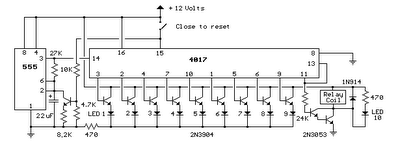
Electronic Cricket Match Game
With the shown values of these components very fast output pulses are generated from the Astable. Output from IC1 passes into the input of IC2 which is the popular Johnson Decade counter CD4017. It has 10 outputs. Of these 8 outputs are used. Output 9 ( pin9) is tied to the reset pin 15 to repeat the cycle. When the input pin 14 of IC2 gets low to high pluses, its output turns high one by one. Resistor R3 keeps the input of IC2 low in stand by state to avoid false indications.
Electronic Cricket Circuit diagram:

When the Push Switch S1 is pressed momentarily, the Astable operates and all the LEDs run very fast sequentially. When S1 is released, any one of the LED stands lit which indicates the status of the match. For example, if LED D7 remains lit, it indicates Sixer and if LED 8 remains lit, it indicates Catch out. Label each LED for its status as shown in the diagram. Pressing of S1 simulates Bowling and Running LEDs indicates running of Batsman.
12 Volt to 32 Volt CT converter DC to DC

Kit converter is also equipped with inputs "SEND" to activate the circuit and also send this interchangeable inputs is connected to the Tape / cd / dvd player of your car. And input "send" is if the non-connected with an output of "send" player car you then connect it to +12 hrs on v from the battery / batteries The series is already in the test kit and has been functioning normally.