Friday, October 17, 2014
Small Circuit Multiband Radio Transmitter CW
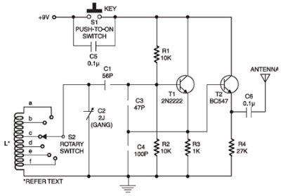
This is a Small Circuit Multiband Radio -Transmitter CW for who wants to learn more about radiofrequency, mainly operating principle from radios transceivers multiband, That circuit consists of a frequency oscillator RF, which is the main component us transmitters and radio receivers.
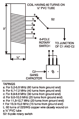
He oscillates for high frequency, he is called variable frequency oscillator or VFO, their frequency may vary of 5.2 MHz to 15 MHz, depending the coil chosen and signal can be received in the band shortwave by any receiver radio.In S1 is used a switch type bell, but can-if use a handler CW, these used by radio amateurs. How antenna should-if use a the type dipole from 1/4 wave.

Thursday, January 30, 2014
2 X 50W ICs amplifier with STK4191
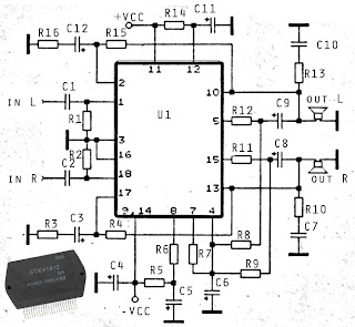
The above is a stereo amplifier circuit based on IC STK4191 with 2 X 50Watt output power 8 ohm impedance. And besides that you can use some of the IC can also be applied in this series include the STK4101, 4111, 4121, 5131, 4141, 4151, 5161, 4171, 4181, and 4191. Required supply voltage from 12 Volt to 35 Volt DC.Part List :
R1 = 22K
R2 = 22K
R3 = 560R
R4 = 56K
R5 = 1K
R6 = 1K
R7 = 100R
R8 = 2K
R9 = 2K
R10 = 4.7R
R11 = 2K2
R12 = 2K2
R13 = 4.7R
R14 = 100R
R15 = 56K
R16 = 560R
C1 = 0.1uF
C2 = 0.1uF
C3 = 100uF
C4 = 100uF
C5 = 100uF
C6 = 0.1uF
C7 = 47uF
C8 = 47uF
C9 = 0.1uF
C10 = 100uF
C11 = 100uF
U1 = STK4191
Tuesday, January 28, 2014
Tips for caring power supply units
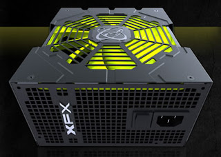
 Power Supply on a computer is an energy source that drives the computer you. With power supply, hardware on the computer is given "power" to can work in accordance with their respective functions Power Supply on a computer to work as a flow modifier (Adapter) from AC current into DC.
Power supply is working on 2 pieces of 5-volt DC voltage and 12 Volt. In a power supply, voltage 12 volt is usually characterized with a yellow cable, while the voltage is 5 Volt is marked with cable red.
Tips to maintain power supply in order to remain durable
1. Make sure you buy the power supply to suit your computer needs. Buy power supply that is guaranteed quality.
2. Make sure when you install a power supply on your computer already in the correct position. Make a tightening of the socket-outlet power supply to the motherboard, hard drive, CDRom, etc.. If you do the installation is not correct it will be fatal and can be a fire or a short-circuit will occur on your hardware.
3. Check your power supply voltages in the BIOS Hardware Monitor or Hardware Management. Is it permissible range qualified. If it does not fit will usually be marked with red writing.
4. Check the condition of the fan at any time at least 3 months. Or, when you have a problem on your computer such as Hang, Restart and Total death. Clean the fan if necessary and give a lubricant (contact cleaner) in as a fan.
5. Do not put your CPU is too close (mepet) with the wall. Because it would cause air circulation fan should be running with the operation will be disrupted.
Monday, January 27, 2014
16W Bridge Amplifier using LM383

The afterward diagram is 16W Bridge audio amplifier circuit. The ambit congenital based 2 pieces of ability IC LM383 in arch connection, so this amplifier is an arch amplifier.
This is an old amplifier, LM383 is discontinued, so this LM383 ability be difficult to find. You can use ECG1232, TDA2002 or TDA2003 as the alter for LM383. Take a agenda that a heatsink bowl is appropriate to abstain overheating on the ICs.
Sunday, January 26, 2014
Multiplexer with TTL IC 74251
Actually you can not bother to design a multiplexer using logic gates because it has many special IC which functioned for a multiplexer.

One of the TTL ICs from the family that you can use to fulfill the function of a multiplexer is IC 74 251. At the IC there are 8 input channels and 3-bit selector and the other lane as a control reset and inverting output. As a note if you are using TTL ICs for your electronic circuit, the voltage supply that is allowed a maximum of 5 volts. So you can be more familiar with the workings of this multiplexer ic, IC74251 consider the truth table below:
C | B | A | G | Y | W |
X | X | X | 1 | Z | Z |
0 | 0 | 0 | 0 | D0 | D0’ |
0 | 0 | 1 | 0 | D1 | D1’ |
0 | 1 | 0 | 0 | D2 | D2’ |
0 | 1 | 1 | 0 | D3 | D3’ |
1 | 0 | 0 | 0 | D4 | D4’ |
1 | 0 | 1 | 0 | D5 | D5’ |
1 | 1 | 0 | 0 | D6 | D6’ |
1 | 1 | 1 | 0 | D7 | D7’ |
Z = High impedance (off) | |||||
D0,D1…D7 = Representing the output of the input lines D | |||||
Saturday, January 25, 2014
Elco tester circuit
Scheme tool as follows, do not smile once, indeed simple. The cost to make it too cheap, not up to $ 1.
 |
| Elco tester circuit |
The workings of this tool based on the nature of the condenser, the condenser ability to store electrons / voltage. Since each condenser has the characteristic charging time and discharging time is different for each size and type dielektrika. Ideally, the larger size, the greater the time required for charging and discharging (charging and disposal charges).
How to use:
- Make sure the position of the switch (SW1) on the discharging position (position A).
- Connect / elco pairs that will be tested, then empty the contents briefly elco by pressing SW2 (approximately 1 to 3 seconds).
- Position the switch in the charging position (position B), the LED will light with a certain time (depending on the value elco). Hold in position B until the LED is not lit (elco is full).
- When the LED is not lit, immediately moved to the position of discharging position (A), the LED will light with a certain time (depending on the value elco tested). Hold in position A until the LED does not turn on again (fill elco is empty).
- The conclusion is quite simple, the larger the size elco, the longer the charging time and dischargingnya (old LED lights up). To calibrate it, readers can use the benchmark elco 10000uF size that can be justified. Only by logic alone writers think readers have understood.
If it is the process of charging and discharging too quickly, the reader can change the value of R1, the greater the value the longer the charging process and discharging.
Good luck and commanded me, the value of its components should not be deleted, do not be wrapped up neatly, keep the same cast in epoxy / cement.
Good luck and commanded me, the value of its components should not be deleted, do not be wrapped up neatly, keep the same cast in epoxy / cement.
Friday, January 24, 2014
Digital Bike Tachometer Circuit
This digital DIY tachometer for bikes uses two reed switches to get the speed information of the bicycle. The reed switches are installed near the rim of the wheel where permanent magnets pass by. The permanent magnets are attached to the wheelspokes and activate the reed switches everytime they pass by it. The speed is digitally displayed.
Electronic bicycle DIY tachometer circuit diagram

The tachometer circuit works according to this principle; the pulses created by the reed contacts are counted within a certain time interval. The resulting count is then displayed and represents the speed of the bike. Two 4026 ICs are used to count the pulses, decode the counter and control two 7-segment LED display. RS flip-flops U3 and U4 function as anti-bounce.
The pulses arrive at the counter’s input through gate U7. The measuring period is determined by monostable multivibrator U5/U6 and can be adjusted through potentiometer P1 so that the tacho can be calibrated. The circuit U1/U2 resets the counters.
Since batteries are used to power the circuit, it is not practical to support the continous display of speed information. This circuit is not continously active. The circuit is activated only after a button is pressed. At least three permanent magnets must be installed on the wheel. The circuit can be calibrated with the help of another precalibrated tachometer.
Subscribe to:
Posts (Atom)