Friday, December 27, 2013

Video IF circuit TV

Video IF circuit
Video IF circuit
The main function of the video IF is to change the 38.0 MHz IF signal into the CVBS signal which later fed into the sound and video to the chroma.


VIF section consists of a series as follows:
IF amplifier
This section serves to strengthen the signal until the signal level is required. IF amplifier is equipped with AGC (Automatic Gain Controller) which controls the strengthening of the IF amplifier so that a constant amplitude output video. Amplifier frequency range from 32 ~ 60 MHz makes this amplifier suitable for applications multistandar.

PLL demodulator and VCO (voltage control oscillator)
IF signal is separated with the help of PLL detector. PLL detector produces a phase reference signal with the IF signal carrier and about 60 KHz bandwidth is determined by PLL loopfilter pin 37. Obtained by comparing the frequency demodulation reference signal with the incoming IF signal. Are required reference frequency (38.0 MHz) generated by the VCO. Appropriate VCO frequency is determined by system calibration using the crystal as a reference. PLL can detect the IF frequency up to ± 1 MHz based on FPLL (Frequency Phase Lock Loop System) which will provide an output signal to the PLL loopfilter for the difference frequency is obtained. If the phase IF signal with a reference signal, the signal is transmitted to the demodulator. Demodulator to control the positive and negative modulation, the selection made ​​by the IIC bus. Low pass filter after the output signal demodulator eliminates the demodulation is not required to process the video.

Video IF schematics


Video Buffer
Video buffer to produce a video output with an amplitude of the right and keep the video output from the noise peak occurring. The bandwidth of the video buffer at least 6 MHz. In the video there are White spot clamp buffer (for positive modulation) and the noise inverter Clamp (for negative modulation) which keeps the amplitude of the video does not exceed the typical price.

Continue[...]

Thursday, December 26, 2013

A 4 Digit Keypad Controller Switch Circuit

A 4-Digit Keypad Controller Switch CircuitA 4-Digit Keypad Controller Switch Circuit

This is a universal version of the Four-Digit Alarm Keypad . I have modified the design to free up the relay contacts. This allows the circuit to operate as a general-purpose switch. It also means that it can be used to control all of my Alarm Circuits. Ive used a SPCO/SPDT relay - but you can use a multi-pole relay if you wish.

The relay is energized by pressing a single key. Choose the key you want to use - and connect it to terminal "E". Choose the four keys you want to use to de-energize the relay - and connect them to "A B C & D". Wire the common to R1 and all the remaining keys to "F".

The Circuit is easy to use. When you press "E" - current through D2 & R9 turns Q6 on - and energizes the relay. The two transistors - Q5 & Q6 - form a "Complementary Latch". So - when you release the key - the relay will remain energized.

To de-energize the relay - you need to press keys "A B C & D" in the right order. When you do so - pin 10 of the IC goes high - and it turns Q4 on through R8. Q4 connects the base of Q6 to ground. This unlatches the complementary pair - and the relay drops out.

Any keys not wired to "A B C D & E" are connected to the base of Q3 by R7. Whenever one of these "Wrong" keys is pressed - Q3 takes pin 1 low and the code entry sequence fails. If "C" or "D" is pressed out of sequence - Q1 or Q2 will also take pin 1 low - with the same result. If you make a mistake while entering the code - simply start again.

The Keypad must be the kind with a common terminal and a separate connection for each key. On a 12-key pad, look for 13 terminals. The matrix type with 7 or 8 terminals will NOT do. With a 12-key pad - over 10 000 different codes are available. If you need a more secure code - use a bigger keypad with more "Wrong" keys wired to "F". A 16-key pad gives over 40 000 different codes.
Continue[...]

Wednesday, December 25, 2013

Battery Charger with Temeperature Sensor

Battery Charger with Temeperature Sensor


Battery with a LM35 temperature sensor on the charger used to monitor the battery temperature is in charge. Battery temperature sensor is needed because the battery temperature will rise at the time in charge. Battery temperature sensor LM35 temperature sensor has high accuracy in monitoring the battery temperature, it is because the temperature sensor LM35 is a temperature sensor that can convert temperature changes into voltage changes linearly.


At the time of the charge a battery will experience changes in temperature, where the battery temperature will begin to rise when the battery began to fill. To avoid over heat the battery, the battery temperature sensor LM35 temperature sensor is required to terminate the battery charging current to avoid overheating.

battery charger schematic with LM35
Battery charger with temperature sensor schematic

On the battery charger circuit temperature sensor with temperature sensor 35 lm above the R1 is used for setting the maximum value of the desired temperature. Therefore, when the temperature was in-charge the battery begins to rise and reach temperatures setup then this series will break the current battery charge.
Continue[...]

Tuesday, December 24, 2013

Class B audio amplifier based on TDA1553

Class B audio amplifier based on TDA1553

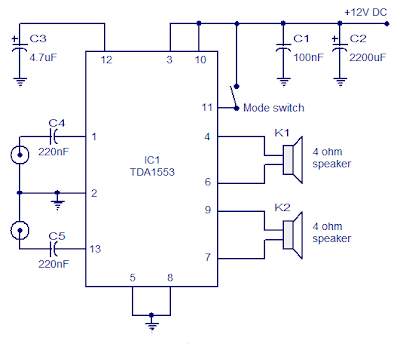
Here is the circuit of a Class B audio amplifier based on TDA1553. TDA1553 is a monolithic audio amplifier class B, containing 2 x 22 watt amplifier in bridge configuration load attached. The amplifier operates from 12V DC and develops intentionaly for car audio applications. The IC also has a lot of good features such as short circuit protection, protection of the load dump, reverse polarity protection, speaker protection, etc.


In the circuit, C5 and C4 are decoupling capacitors C3 input, while setting the delay for speaker protection. C1 and C2 are filter capacitors of the offer.


Notes :

  • Assemble the circuit on a good quality PCB.
  • Use 12V DC for powering the circuit.
  • The circuit can deliver 22W per channel into 4 ohm speakers.
  • Fit the IC with a proper heat sink.
Continue[...]

Monday, December 23, 2013

Understanding Audio Amplifiers


Audio amplifiers are by the side of the very spirit of each at your house plays practice. to the same degree the quality and output power rations of at presents loudspeakers multiply, so puzzle out the stress of audio amps. It is fast to pick an amplifier known the obese come to of models and designs. I bidding explain more or less of the nearly everyone customary amplifier designs such so "tube amps", "linear amps", "division-AB" and "class-D" as well as "class-T amps" to help you understand some of the provisos commonly used by amplifier manufacturers. This conductor ought to and help you symbol not permitted which topology is ideal intended for your specific attention.

Simply set, the intent of an audio amplifier is to convert a low-power audio imply into a soaring-power audio signal. The high-power signal is huge an adequate amount to drive a loudspeaker amply loud. wearing order to solve to, an amp uses single before additional elements which are controlled by the low-power suggest to generate a large-power signal. These elements range from tubes, bipolar transistors to FET transistors.

High Power Amplifier
Audio Power Amplifier
Tube amplifiers used to occur everyday a little decades before. A tube is able to control the current stream according to a control voltage which is connected to the tube. Unfortunately, tube amplifiers state a somewhat towering amount of distortion. Technically speaking, tube amplifiers motivation introduce elevated harmonics into the sign. However, this characteristic of tube amps still makes these standard. Many nation explain tube amps for instance having a kindhearted sound versus the cold sound of solid state amps.

an added drawback of tube amps, though, is the low power efficiency. The majority of power which tube amps consume is being degenerate as leg and lone a portion is being converted into audio power. additionally, tubes are quite expensive to get on to. like this tube amps experience mostly been replaced by solid-state amps which I motivation look on then.

Solid state amps reinstate the tube with semiconductor elements, typically bipolar transistors or else FETs. The most primitive type of solid-state amps is famous to the same degree category-A amps. modish class-A amps a transistor controls the current arise according to a lesser-level show. various amps avail yourself of a pointer machinery in order to underestimate the choral distortion. Class-A amps produce the lowest distortion and regularly furthermore the lowest amount of clatter of one amplifier architecture. If you need ultra-low distortion afterward you be supposed to take a closer look by panache-A models. The chief drawback is with the purpose of like to tube amps class A amps have very low efficiency. like a upshot these amps require corpulent heat up sinks to dissipate the shrunken energy and are typically rather bulky.

Class-AB amps pick up on the efficiency of class-A amps. They use a string of transistors to break up the large-level signals into two separate areas, every one of which can remain greater than before further efficiently. when such, style-AB amps are regularly less important than class-A amps. However, this topology adds selected non-linearity before distortion appearing in the region wherever the sign switches involving individuals areas. As such class-AB amps typically tolerate top distortion than class-A amps.

Class-D amps upgrade on the efficiency of rank-AB amps even advance by using a switching transistor which is constantly being switched on before inedible. thus this switching stage hardly dissipates a few power and along these lines the power efficiency of class-D amps commonly exceeds 90%. The switching transistor is being controlled by a pulse-width modulator. The switched overweight-level gesticulate has to happen lowpass filtered in the field of order to remove the switching signal and recover the audio signal. Due to non-linearities of the pulse-width modulator and the switching transistor itself, categorize-D amps by nature be inflicted with amongst the highest audio distortion of every audio amplifier.

To solve the question of exalted audio distortion, newer switching amplifier designs incorporate response. The better indication is compared with the real McCoy low-level signal and errors are corrected. A well-recognized architecture which uses this type of pointer is known being "course group-T". Class-T amps before "t amps" do audio distortion which compares with the audio distortion of class-A amps while by the side of the same type offer the power efficiency of class-D amps. along these lines t amps can remain made tremendously undersized and still complete elevated audio fidelity.
Continue[...]

Sunday, December 22, 2013

Car Battery Charger 12Volt Circuit Diagram

Car Battery Charger 12Volt Circuit DiagramCar Battery Charger 12Volt Circuit Diagram

The aloft circuit claimed accept adeptness to anticipate array blackmail that accomplish electrolyte absent due to evaporation. This ambit will annihilate the problems by ecology the battery’s action of allegation through its attendant ascendancy ambit by applying a aerial allegation accepted until the array is absolutely charged. Back charging is complete, it turns on the red LED (LD2) and deactivates the charging circuit.

This ambit is fatigued to allegation 12V batteries ONLY. Certain accent should be taken back base up this circuit. They are the access of the agent to the ambit board, and those bartering accepted to the array actuality charged. These access should be fabricated with cables accepting a ample cross-sectional breadth to anticipate voltage-drop and calefaction accession back accepted flows through them.

Continue[...]

Saturday, December 21, 2013

TDA2003 Car amplifier


This is a very popular series of amplifiers audio users who require maximum aduio results and of course with a relatively cheap price. This circuit requires a minimum voltage and maximum 9 Volt and 30 Volt. This amplifier circuit using ic TDA2003, which is used in car audio power, because of making these amplifiers can easily be made on each speaker of the amplifier. By using ic and component quality is very good circuit used separately. The circuit can be seen below.


Technical information:
Supply voltage = 12V
Output             = 10W 

Continue[...]