Saturday, December 7, 2013
9 Channels Sensor Switch
This sensor switch circuit diagram is designed using CMOS components. This sensor switch circuit has nine channels and consist of only three integrated circuits and some resistors. Due to high input impedance, 74HC147 allows to use of 4.7 M resistors to create a logic level "high" to sensor inputs. When one sensor is touched, the resulting low resistance to ground circuit causes IC1 to read a logical level L.
9 Channels Sensor Switch Circuit Diagram
 If several sensors are touched simultaneously, priority encoder delivers 4-bit code corresponding to the sensor with the highest number.
9 Channels Sensor Switch Circuit Diagram

Friday, December 6, 2013
Reducing Treble tone circuit
Treble reducer circuit above is an example of a simple circuit and is suitable to be used as experimental material and analysis of the workings of the circuit.

As I mentioned earlier the bass reducer series, this series actually has the same working principles with a series of bass reducer. Where these circuits utilize capacitors nature of the charge and discharge. The difference of the damping function obtained from the difference of the capacitor. If the series bass reducer series capacitors are mounted on the op-amp input lines, while in this treble reducer series capacitors are mounted parallel with the strengthening of the op-amp prisoners. Installation of this circuit has a parallel in the work analysis in contrast with the installation of the series on a series of bass reducer. The difference is that the installation of the series, so we URLs that are easy to understand how a wire working capacitors for high frequency signal, so with high frekuesni so automatic signal to be passed to the output terminal by a capacitor. But if we put a parallel between the output capacitor with the terminals, then automatically because the capacitor is considered as a wire so the voltage on the capacitor is near 0 volts, so the output voltage will also follow the voltage on the capacitor because they connect parallel. As with the low frequency signal, the capacitor is considered open and makes voltage wire that fell to him is to approach the input voltage. To understand how the capacitor can be regarded as a wire or an open switch I mentioned in my post about the working principles of capacitors and a series of bass reducer.
Indeed, when examined in detail, not only the capacitors that play a role here but the component resistors and op-amp also affect. But I can confirm that the main function is performed by a capacitor reduction. Series resistors are intended to be installed that will flow into the capacitor can be adjusted so that it influences the charge and discharge the capacitor will make the appropriate damping.
Take a look at the picture above the treble reducer circuit and also the image output signal. There are two function generator as input and has a signal with different frequencies. The first signal of amplitude 1 volt and low frequencies, the two signals with an amplitude of 1 volt and with high frequency. At the time of our input select switch position to the relationship with the input low frequency signal, the signal output will be nearly equal to the input signal such as no change. Whereas if we switch position to link high-frequency input signal then the output signal amplitude will be damped near 0 volts.
Example treble reducer circuit is very simple and can you develop more in accordance with the desires and your needs. At least with understanding the working principle of this circuit we can apply a time when we are required to perform the function of damping trebele.
Thursday, December 5, 2013
Quad Audio Amplifier Circuit diagram with TDA7831 4×25W
 Quad Audio Amplifier Circuit diagram with TDA7831 4×25W
The afterward is a cloister amplifier circuit (amplifier with four inputs and four outputs) based TDA7381. This amplifier is advised for car audio system, but you can additionally use this ambit for added purposes. This ambit has a architecture actual simple and actual accessible to build.
Wednesday, December 4, 2013
Honda Motorcycle CB750F Ciruit Diagram
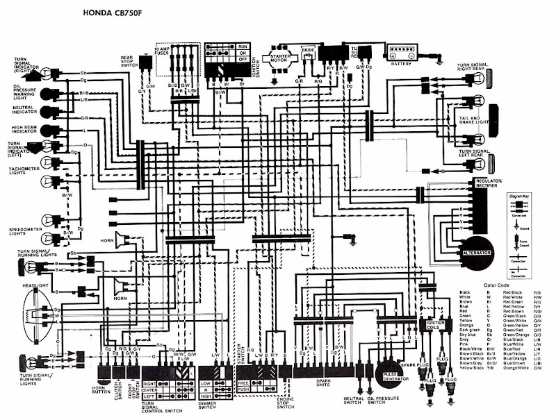 Honda Motorcycle CB750F Ciruit Diagram
The afterward account shows the electrical base affiliation diagram for Honda Motorcycle CB750F. It shows the affiliation amid Honda genitalia such as the appropriate about-face arresting indicator light, oil burden admonishing light, aloof indicator, aerial axle indicator, about-face arresting indicator, tachometer lights, speedometer lights.
turn/signal active lights, headlight, about-face signal/running light, horn and horn button, clamp switch, advanced stop switch, about-face arresting ascendancy switch, dimmer switch, agent stop switch, atom units, aloof switch, oil burden switch, rear stop switch, fuses, agitation switch, amateur motor, battery, about-face arresting appropriate rear, appendage and anchor light, about-face arresting larboard rear, regulator/rectifier, alternator, agitation coils, beating generator, atom plugs, and additionally the blush code.
turn/signal active lights, headlight, about-face signal/running light, horn and horn button, clamp switch, advanced stop switch, about-face arresting ascendancy switch, dimmer switch, agent stop switch, atom units, aloof switch, oil burden switch, rear stop switch, fuses, agitation switch, amateur motor, battery, about-face arresting appropriate rear, appendage and anchor light, about-face arresting larboard rear, regulator/rectifier, alternator, agitation coils, beating generator, atom plugs, and additionally the blush code.
Tuesday, December 3, 2013
High HiFi Power Amplifier with MOSFET
Circuit amplifier "High Power HiFi Power Amplifier With MOSFET" is capable of giving the output power to the load speakers 240Watt and 380Watt 8Ohm to load 4Ohm speakers.
Voltage source to a series of power amplifiers "High Power HiFi Power Amplifier With MOSFET" This is a CT 25V 50V 25V to 50V CT of transformer CT. In making this power amplifier needs to be installed heatsinks on the power amplifier (MOSFET) in order to avoid excessive heat. The series of power supply to power amplifer can use the transformer 5A-20A and 35A mounted diode bridge and capacitors for a minimum of 2x 10.000uF electrolit. Details for the power amplifier circuit can be seen in the following figure.
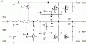
High Power Series HiFi Power Amplifier With MOSFET can modify to increase power output by doubling the final power amplifier is based on the diiginkan. Power generated from doubling the final power amplifier will also double its power output of power amplifier circuit "High Power HiFi Power Amplifier With MOSFET" it.
Monday, December 2, 2013
Black Box Lightshow Circuit
Black Box Lightshow Circuit Heres the circuit for the Black Box Lightshow. Im pretty sure its right. And now, an explanation: The LED array is shown here as individual diodes, though I used six 5x7 LED arrays, each one is 2" tall.

They are arranged as 14 rows and 15 columns. The left channel is 8 columns and the right channel is 7 columns. The extra column from the left channel is the center column and gives nice symmetry. Not shown here is that on the right channel, the first column (pin 1) is not used so that the other columns are equal. The LM3914 is a Dot/Bar Display Driver.
It does all the heavy lifting of converting the audio signal into a series of bars - these are typically used as digital meters. The potentiometer sets the sensitivity of the display. Since the rows are multiplexed (see below), each column is only driving one LED at a time. I only show the left channel here, the right channel is identical, and they share the level setting potentiometer. The right portion of the diagram is a 555 clock, a 7493 4-bit counter and a 74154 4-to-16 line decoder/demultiplexer.
This is the "sweep" part of the display that cycles through each row of LEDs. The potentiometer at the top controls the sweep speed. The net result is that the 74154 is cycling through the pins/rows, grounding each in succession. Note that I only have 14 rows, but it is counting to 16 each time. No big deal, it doesnt affect the perceived output at all. The N2907 transistors are there to provide enough power for all the LEDs. Potentially, all 15 LEDs in a row can be lit up at once, so the transistors make sure there is enough juice. Unfortunately, I lost the original plans during a garage cleaning after I built the electronics (the box took another few months before I got around to it). I opened it up and reverse engineered my own work. I wont guarantee it, but it sure looks right to me. The one weird thing I found is that I dont have power going to pin 8 of the 555 (as shown here), but it works fine - go figure. Also, Im not 100% sure I got the polarity of the LEDs right, sorry about that. I would recommend testing that out first.
Sunday, December 1, 2013
BTL Stereo Amplifier TDA7052 3
This is BTL stereo power amplifier with basic amplifier on IC TDA7052 / TDA7053
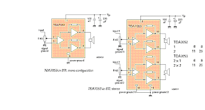
Continue[...]
Subscribe to:
Posts (Atom)