Wednesday, October 24, 2012

Oscillation Monitor

The circuit in the diagram was originally designed to monitor an oscillator, but can also be used as a general-purpose level indicator for a.c. signals. It is based on a quadruple IC containing four NAND gates. Only three of the gates are used, making the fourth free for other purposes. All the gates have a Schmitt trigger input. When a 5 V supply is used, the Type 74HC132 is recommended; for higher voltage, a Type 4093. Note, however, that these two ICs have different pinouts. In the diagram, the differing pins of a 4093 are shown in brackets. The signal to be monitored is applied to the input of the first gate via capacitor C1. Resistor R2, in conjunction with the protection diode in the IC, guards the input to high voltages.

In the absence of a signal, resistor R1 holds the input high so that the output of the gate is low. When a signal of sufficient strength is received, the input of the gate goes low during the negative half cycle of the signal, so that the output of the gate goes high in rhythm with the input signal. However, the Schmitt trigger converts sinusoidal signals into rectangular ones, which charge capacitor C3 via diode D1. When the potential across C3 exceeds the threshold at the input of the second gate, this gate also toggles. The output of the second gate is then low, which disables the third gate, which functions as an oscillator. When the level of the input signal drops, C3 is discharged via R3.

Oscillation MonitorThe potential across the capacitor then no longer exceeds the threshold at the input of IC1b, whereupon IC1c is enabled and the LED flashes The LED may be connected as shown or as indicated by the dashed line. As shown, the diode remains off when there is an input signal of sufficient strength and begins to flash when the signal fails or its level drops. When the diode is linked to earth, it is on continuously when there is an input signal, and begins to flash when the input drops. When a 5 V power supply is used, R5 = 1 kΩ, and the circuit draws a current, including that of the LED, of 3mA. The frequency of the input signal may lie between 10 Hz and 10 MHz. When a 9–12 V supply is used, the value of R5 must be altered as necessary.

Owing to the 4093 being slower than the 74HC132, the upper frequency of the input signal is then limited to 3 MHz. When the wiper of P1 is at the level of the supply voltage, the response threshold, USS, lies between 3.5 V (when Ub =5V) and 7 V (when Ub =12V). When the wiper is moved away from the positive supply line, USS (max) is 1.5 V (when Ub = 5 V). The response threshold is quite precise: a drop in the input signal level of 50–100 mV is sufficient to disable the input. When the input level is too high, a preset across the input terminals enables the level to be reduced to a value that lies in the desired range above the response threshold.
Continue[...]

Simple Voltmeter

This circuit provides a simple means to determine the voltage of a low-impedance voltage source. It works as follows. P1, which is a 1-W potentiometer, forms a voltage divider in combination with R1. The voltage at their junction is buffered by T1, and then passed to reference diode D1 via R3. D1 limits the voltage following the resistor to 2.5 V. An indicator stage consisting of T2, R4 and LED D2 is connected in parallel with D1. As long as the voltage is not limited by D1, the LED will not be fully illuminated. This is the basic operating principle of this measurement circuit.
Simple Voltmeter circuit diagram
Continue[...]

Simple MD Catridge Preamplifier

Phonographs are gradually becoming a rarity. Most of them have had to yield to more advanced systems, such as CD players and recorders or (portable) MiniDisc player/recorders. This trend is recognized by manufacturers of audio installations, which means that the traditional phono input is missing on increasingly more systems. Hi-fi enthusiasts who want make digital versions of their existing collections of phonograph records on a CD or MD, discover that it is no longer possible to connect a phonograph to the system.

Simple MD Catridge Preamplifier circuit diagramHowever, with a limited amount of circuitry, it is possible to adapt the line input of a modern amplifier or recorder so that it can handle the low-level signals generated by the magnetodynamic cartridge of a phonograph. Of course, the circuit has to provide the well-known RIAA correction that must be used with these cartridges. The preamplifier shown here performs the job using only one opamp, four resistors and four capacitors. For a stereo version, you will naturally need two of everything. Any stabilized power supply that can deliver ±15V can be used as a power source.
Continue[...]

High Side Current Measurements

It’s always a bit difficult to measure the current in the positive lead of a power supply, such as a battery charger. Fortunately, special ICs have been developed for this purpose in the last few years, such as the Burr-Brown INA138 and INA168. These ICs have special internal circuitry that allows their inputs to be connected directly to either end of a shunt resistor in the lead where the current is to be measured. The shunt is simply a low-value resistor, across which a voltage drop is measured whenever a current flows. This voltage is converted into an output current Io by the IC.

This current can be used directly, or it can be converted into a voltage by means of a load resistor RL. In the latter case, the ‘floating’ measurement voltage across the shunt is converted into a voltage with respect to earth, which is easy to use. The value of RL determines the gain. A value of 5 kΩ gives 1×, 10 kΩ gives 2×, 15 kΩ gives 3× and so on. It all works as follows. Just like any opamp, this IC tries to maintain the same potential on its internal plus and minus inputs. The minus input is connected to the left-hand end of the shunt resistor via a 5-kΩ resistor.

High Side Current Measurements Circuit DiagramWhen a current flows through the shunt, this voltage is thus lower than the voltage on the plus side. However, the voltage on the plus input can be reduced by allowing a small supplementary current to flow through T1. The IC thus allows T1 to conduct just enough to achieve the necessary lower voltage on the plus input. The current that is needed for this is equal to Vshunt / 5 kΩ. This transistor current leaves the IC via the output to which RL is connected. If the value of RL is 5 kΩ, the resulting voltage is exactly the same as Vshunt. The IC is available in two versions.

The INA138 can handle voltages between 2.7 and 36 V, while the INA168 can work up to 60 V. The supply voltage on pin 5 may lie anywhere between these limits, regardless of the voltage on the inputs. This means that even with a supply voltage of only 5 V, you can make measurements with up to 60 V on the inputs! However, in most cases it is simplest to connect pin 5 directly to the voltage on pin 3. Bear in mind that the value of the supply voltage determines the maximum value of the output voltage. Also, don’t forget the internal base-emitter junction voltage of T1 (0.7 V), and the voltage drop across the shunt also has to be subtracted.
Continue[...]

Measuring Inductors

Often you find yourself in the position of needing to wind your own coil for a project, or maybe you come across an unmarked coil in the junk-box. How can you best find out its inductance? An oscilloscope is all you need. Construct a resonant circuit using the coil and a capacitor and connect it to a square wave generator (often part of the oscilloscope itself) Adjust the generator until you find the resonant frequency f.

Measuring Inductors circuit diagramWhen C is known (1000pF) the inductance L may be calculated from: L=1/(4π2.f2.C) If you are also interested how good the coil is i.e. what is its quality factor or Q, you can use the oscilloscope again. If the level of the damped oscillation drops to 0.37 (= 1/e) of the maximum after about 30 periods, then the Q factor of the coil is about 30. The Q factor should be measured at the intended operating frequency of the coil and with its intended capacitor. The coupling capacitor should by comparison be a much smaller value.
Continue[...]

1kH Synthetic Inductor

Inductors can be mimicked quite easily using operational amplifiers. The circuit shown here was developed to have an inductance of 1000 H (say, one thousand Henry) with good damping. Using this design you can build a resonant circuit with a center frequency of less than 1 Hz. The slow behavior allows you to use conventional measuring instruments to investigate the circuit in real time. The circuit can also be used as part of a filter design. Opamp1 operates as an Integrator, Opamp2 as a difference amplifier.

1kH Synthetic Inductor Circuit DiagramThe output voltage of Opamp2 is equal to the voltage drop across R1 and P1, which is proportional to the output current. This voltage is differentiated by Opamp1, C1 and R2. The net effect is that the circuit behaves as an inductor. P1 allows adjustment of the inductance value. P2 allows adjustment of the Q factor of the coil by altering the symmetry of the difference amplifier and with it the stability of the circuit.
Continue[...]

Sunday, October 21, 2012

Sound Effects Generator 2

This circuit uses the Holtek HT2884 IC to produce 8 different sound effects. All sound effects are generated internally by the HT2884 IC. Power is a 3 Volt battery, but the IC will work with any voltage between 2.5 and 5 Volts. Switch S1 is the on / off switch.
Sound Effects Generator 2 Circuit Diagram:
Sound Effects-Generator-2-Circuit Diagram
The output at pin 10 is amplified and drives a small 8 ohm loudspeaker. Pressing S3 once will generate all the sounds, one after another. S2 can be used to produce a single sound effect, next depression gives the next sound effect. There are 2 lazer guns, 1 dual tone horn sound, 2 bomb sounds, 2 machine gun sounds and a rifle shot sound. Standby current is about 1 uA at 3 Volt, so battery life is very economical.

The IC may be obtained from Maplin Electronics order code AZ52G
Continue[...]

Solid State Relay - Required Only 50uA Drive Current

This circuit demands a control current that is 100 times smaller than that needed by a typical optically isolated solid state relays. It is ideal for battery-powered systems. Using a combination of a high current TRIAC and a very sensitive low current SCR, the circuit can control about 600 watts of power to load while providing full isolation and transient protection.


Continue[...]

Sunday, October 14, 2012

TV Remote Control Jammer

This circuit confuses the infra-red receiver in a TV. It produces a constant signal that interferes with the signal from a remote control and prevents the TV detecting a channel-change or any other command. This allows you to watch your own program without anyone changing the channel !!    The circuit is adjusted to produce a 38kHz signal. The IR diode is called an Infra-red transmitting Diode or IR emitter diode to distinguish it from a receiving diode, called an IR receiver or IR receiving diode. (A Photo diode is a receiving diode).


Circuit Project: TV REMOTE CONTROL JAMMER Circuit

There are so many IR emitters that we cannot put a generic number on the circuit to represent the type of diode. Some types include: CY85G, LD271, CQY37N (45¢), INF3850, INF3880, INF3940 (30¢). The current through the IR LED is limited to 100mA by the inclusion of the two 1N4148 diodes, as these form a constant-current arrangement when combined with the transistor and 5R6 resistor.
Continue[...]

Simple But Reliable Car Battery Tester

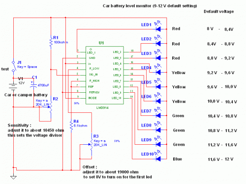
This circuit uses the popular and easy to find LM3914 IC. This IC is very simple to drive, needs no voltage regulators (it has a built in voltage regulator) and can be powered from almost every source. This circuit is very easy to explain: When the test button is pressed, the Car battery voltage is feed into a high impedance voltage divider. His purpose is to divide 12V to 1,25V (or lower values to lower values).

This solution is better than letting the internal voltage regulator set the 12V sample voltage to be feed into the internal voltage divider simply because it cannot regulate 12V when the voltage drops lower (linear regulators only step down). Simply wiring with no adjust, the regulator provides stable 1,25V which is fed into the precision internal resistor cascade to generate sample voltages for the internal comparators. Anyway the default setting let you to measure voltages between 8 and 12V but you can measure even from 0V to 12V setting the offset trimmer to 0 (but i think that under 9 volt your car would not start).

Circuit Project: Simple but reliable car battery tester

There is a smoothing capacitor (4700uF 16V) it is used to adsorb EMF noise produced from the ignition coil if you are measuring the battery during the engine working. Diesel engines would not need it, but I'm not sure. If you like more a point graph rather than a bar graph simply disconnect pin 9 on the IC (MODE) from power. The calculations are simple (default)
For the first comparator the voltage is : 0,833 V corresponding to 8 V
* * * * * voltage is : 0,875 V corresponding to 8,4 V
for the last comparator the voltage is : 1,25 V corresponding to 12 V
Have fun, learn and don't let you car battery discharge... ;-)
author: Jonathan Filippi
e-mail: jonathan.filippi@virgilio.it
Continue[...]

Solar-Powered High Efficiency Charger

This is a simple NiCd battery charger powered by solar cells. A solar cell panel or an array of solar cells can charge a battery at more than 80 % efficiency provided the available voltage exceeds the ‘fully charged’ battery voltage by the drop across one diode, which is simply inserted between the solar cell array and the battery. Adding a step-down regulator enables a solar cell array to charge battery packs with various terminal voltages at optimum rates and with efficiencies approaching those of the regulator itself. However, the IC must then operate in an unorthodox fashion (a.k.a. ‘Elektor mode’) regulating the flow of charge current in such a way that the solar array output voltage remains near the level required for peak power transfer. Here, the MAX639 regulates its input voltage instead of its output voltage as is more customary (but less interesting).

Circuit diagram:

Solar-Powered High Efficiency Charger Circuit Diagram

The input voltage is supplied by twelve amorphous solar cells with a minimum surface area of 100 cm2. Returning to the circuit, potential divider R2/R3 disables the internal regulating loop by holding the V-FB (voltage feedback) terminal low, while divider R1/R2+R3 enables LBI (low battery input) to sense a decrease in the solar array output voltage. The resulting deviation from the solar cells’ peak output power causes LBO (low battery output) to pull SHDN (shutdown) low and consequently disable the chip. LBI then senses a rising input voltage, LBO goes high and the pulsating control maintains maximum power transfer to the NiCd cells.

Current limiting inside the MAX639 creates a ‘ceiling’ of 200 mA for I out. Up to five NiCd cells may be connected in series to the charger output. When ‘on’ the regulator chip passes current from pin 6 to pin 5 through an internal switch representing a resistance of less than 1 ohm. Benefiting from the regulator’s low quiescent current (10 microamps typical) and high efficiency (85 %), the circuit can deliver four times more power than the single-diode configuration usually found in simple solar chargers. Coil L1 is a 100-µH suppressor choke rated for 600 mA.
Author: D. Prabakaran - Copyright: Elektor July-August 2004
Continue[...]