Saturday, November 30, 2013
6 Watt Audio Amplifier Schematic Circuit with TDA1519
 6 Watt Audio Amplifier Schematic Circuit with TDA1519
The audio amplifier circuit is on the TDA1519 amplifier IC that is based in audio applications, which is not a aerial achievement ability can be used. The ambit TDA1519 is a ability of 2×6 watts.
The TDA1519 is an amplifier congenital Class B dual-output advance in a 9-by-line (SIL) artificial amalgamation boilerplate achievement is primarily developed for car radio applications.
Key Features of the audio amplifier IC TDA1519 are: Requires few alien components, anchored gain, acceptable bounce drive, aphasiac / standby mode, thermal protection, about-face polarity safe. Tda1519 amplifier ability rating, 14.4 volts.
Friday, November 29, 2013
NE555 IC Timer
 The 555 gets its name from the three 5-k Ohm resistors used in typical early implementations. It is still in wide use, thanks to its ease of use, low price and good stability. As of 2003[update], 1 billion units are manufactured every year.
Thursday, November 28, 2013
Simple 4 Channel Video Amplifier Using NJM2582
Simple 4 Channel Video Amplifier Circuit diagram

Wednesday, November 27, 2013
Volt meters ampere meter with PIC
 |
| Volt meters & ampere meter with PIC |
Tuesday, November 26, 2013
Simple Water Activated Alarm
Simple Water Activated Alarm Circuit diagram :

An On/Off switch is provided and remember to use a non-reactive metal for the probe contacts. Gold or silver plated contacts from an old relay may be used, however a cheap alternative is to wire alternate copper strips from a piece of veroboard. These will eventually oxidize over but as very little current is flowing in the base circuit, the higher impedance caused by oxidization is not important. No base resistor is necessary as the transistor is in emitter follower, current limit being the impedance at the emitter (the oscillator circuit).
Monday, November 25, 2013
Basically the DAC circuit
Since the discovery of Silicon and Germanium semiconductor material then quickly there was a revolution in terms of simplicity and accuracy of an electronic circuit. Besides, with the implementation of digital circuits will support at all in terms of data storage and mobility. Lots of data can now be operated with a computer is a data converted from analog signals. For example a voice signal or analog form of video can be played and stored using a computer after analog signals are converted into digital data.
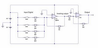
In the DAC circuit above uses two LM741 Op-Amp IC is often used as an amplifier. IC1 to function as a producer of analog signal is reversed, and turned back IC2 function signal from IC1. Basic circuit of the DAC is a common amplifier circuit, only used a variation of several resistors in order to obtain a regular reinforcement signal. Rules that must be understood from this DAC circuit is the value of resistors on the input op-amp. The value for the resistor at high bit (R4) should be 2x the amplifier resistor (R5), then for the next bit should be 2x the resistor value at a higher bit. So if the circuit uses 4-bit DAC is the unit bit (lowest bit) is the value of bits to be 8x-4. From the picture above the unit bit is represented by resistor 80 Kohm.
Sample Conditions:
- 0001 (1) = switch SW1 closed and others opened, the voltage output produced is (5K/80K) x 9 volt = 0.5625 volts
- 0010 (2) = SW2 is closed and another switch is opened, the output voltage is (5K/40K) x 9 volts = 1.125 volts
- 0011 (3) = SW1 and SW2 is closed and another switch is opened, the voltage output is (5K/Rparalel 80K and 40K) x 9 volt = (5K/26, 667K) X 9 volt = 1.6875 volts
- 1000 (8) = SW4 is closed and another switch is opened, the output voltage is (5K/10K) x 9 volts = 4.5 volts.
From the above calculation can be concluded that unlicensed with a voltage output proportional to the input conditions, eg for 1 decimal is 0.5625 volts then, decimal 2 = 2 x 0.5625 = 1125 volts, decimal 3 = 3 x 0.5625 = 1.6875 volts, and so on. This condition is due to the parallel relationship between the input resistors.
Sunday, November 24, 2013
Stereo 9 Volt power amplifier circuit
Here I will explain about the necessary voltage and power amplifier output. The voltage should have at least approximately 9Volt 30Volt voltage and maximum voltage on the DC current. For maximum output of 2 X 2Watt with impedance 8-16 ohm. Because this amplifier circuit using ic and ic is used have the equation, so that if used different ic, then the required output voltage and also differ depending ic respectively.

Part List :
Resistor
R1 = 1M
R2 = 1M
R3 = 1K
R4 = 1K
R5 = 100K
R6 = 100K
R7 = 1R
R8 = 1R
Capacitor
C1 = 1uF
C2 = 220uF
C3 = 1uF
C4 = 100uF
C5 = 5uF
C6 = 5uF
C7 = 0.1uF
C8 = 220uF
C9 = 220uF
C10 = 0.1uF
IC
U1 = ULN2274B , ULN2277 , ULN2278B
Saturday, November 23, 2013
Auto Sound Systems are an Investment in your Car Make it Great
 Many of us find that lugging around an MP3 player with all of our favorite tunes (or at least most of them-with up to 40 gigs of hard drive space it might take a while to fill completely) is much easier and more practical than attempting to lug around a huge case of CDs. It is also great for those of us who find ourselves disappointed when we purchase CDs only to find that we really only like one or two songs. Now we can simply download the songs we know and love while avoiding those we are uncertain about or at least waiting until more songs come out before deciding whether or not to purchase the entire collection of songs. Having an auto sound system that allows you to enjoy the convenience of simply plugging in either your MP3 player or a memory card or stick in order to have your favorite songs at your finger tips at all times is fantastic.
Friday, November 22, 2013
Parking Light Switch
Parking Light Switch Circuit Diagram

Notes:
This is a very simple light switching circuit using a single transistor and relay to control an external mains powered light. Relay RLA is drawn with two changeover contacts, but a relay with two make contacts can also be used. The contacts MUST be rated at 240V AC and at least 3 Amp (or higher) to safely switch loads of up to 500 Watts. Once energized the relay latches through contacts RLA1 and the external lamp is switched via contact RLA2.
Setting Up:
Wait until darkness and shine your vehicles headlights at the ORP12 Photocell. Adjust the 100k potentiometer until the relay triggers. Turn off the headlights and press S2 to turn off the relay. The external light should go off. It may be necessary to place a plastic tube of about 1 inch in length so that only light emitted by a cars headlights reaches the photocell. This will prevent unwanted triggering.
The light can also be manually controlled by pressing S1 which will latch the circuit, and S2 will turn off the lamp again.
Thursday, November 21, 2013
Solar Powered Animal Scarer
The circuit has an LDR controlled oscillator built around the Binary counter IC CD 4060.The functioning of the IC is controlled through its reset pin 12. During day time, LDR conducts and keeps the reset pin of IC high so that it remains dormant. During night, LDR cease to conduct and the reset pin will be grounded through VR1. This triggers the IC and it stats oscillating using the components C1 and VR2. Output pins 7, 5 and 4 are used to power the LEDs strings.
VR1 adjusts the sensitivity of LDR and VR2, the flashing rate of LEDs. High bright Red, Blue and White LEDs are used in the circuit to give brilliant flashes. Red LEDs flash very fast, followed by blue and then White. White LEDs remains on for few seconds and provide light to a confined area. More LEDs can be added in the strings if desired. The circuit can also function with 12 volt DC.
Animal Repellent Circuit diagram:

The circuit uses a solar powered battery power supply. During daytime, battery charges through R1 and D1.Green LED indicates the charging mode. During night time current from the solar cell decreases and D1 reverse biases. At the same time D2 forward biases to provide power to the circuit. Resistor R1 restricts the charging current and the high value capacitor C1 is a buffer for current.
Animal Scarer Solar Power Supply Circuit diagram:

Wednesday, November 20, 2013
Stereo Headphone Amplifier

Component Stereo Headphone Amplifier
P1 = 22K
R1 = 18K
R2 = 68K
R3 = 68K
R4 = 68K
R5 = 18K
R6 = 68K
C1 = 4.7uF/25v
C2 = 4.7uF/25v
C3 = 22pF
C4 = 220uF/25v
C5 = 220uF/25v
C6 = 4.7uF/25v
C7 = 22pF
C8 = 220uF/25v
J1 = 3.5mm Stereo Jack
B1 = 9V Alkaline Battery
IC1 = NE5532 or NE5534
SW1 = SPST Toggle Switch
Tuesday, November 19, 2013
TDA2004 stereo bridge audio amplifier


Monday, November 18, 2013
Strain Gauge measure the pressure or weight
Sunday, November 17, 2013
Electronic Components As Light Sensor
 |
| Electronic Components As Light Sensor |
Saturday, November 16, 2013
Dual Mode Microphone Pre Amplifier
R1 = R7 = 4k7; R2 = R3 = 47k; R4 = 39k; R5 = R6 = 100k; R8 = 220; R9 = 10k; R10 = 2k2 (all 1/8 Watt). VR1 = 10k
horizontal pre-set. C1 = 47uF; C2 = C3 = C4 = 10uF (all 10V or greater, miniature radial electrolytics). Tr1 = Tr2 = Tr3 = Tr4 = Tr5 = BC108, BC184, BC547, ZTX337 or similar low-power (preferably low noise) NPN transistor
Friday, November 15, 2013
Elco tester circuit
 |
| Elco tester circuit |
- Make sure the position of the switch (SW1) on the discharging position (position A).
- Connect / elco pairs that will be tested, then empty the contents briefly elco by pressing SW2 (approximately 1 to 3 seconds).
- Position the switch in the charging position (position B), the LED will light with a certain time (depending on the value elco). Hold in position B until the LED is not lit (elco is full).
- When the LED is not lit, immediately moved to the position of discharging position (A), the LED will light with a certain time (depending on the value elco tested). Hold in position A until the LED does not turn on again (fill elco is empty).
- The conclusion is quite simple, the larger the size elco, the longer the charging time and dischargingnya (old LED lights up). To calibrate it, readers can use the benchmark elco 10000uF size that can be justified. Only by logic alone writers think readers have understood.
Good luck and commanded me, the value of its components should not be deleted, do not be wrapped up neatly, keep the same cast in epoxy / cement.
Thursday, November 14, 2013
Basic LM35 temperature sensor circuit

Wednesday, November 13, 2013
Guitar Amplifier Circuit Diagram 100W
 Guitar Amplifier Circuit Diagram 100W
The ability amp lath has remained banausic back it was aboriginal appear in 2002. It absolutely isn’t broken, so there’s no acumen to fix it. The photo beneath shows a absolutely accumulated lath (available as apparent as M27). Application TIP35/36C transistors, the achievement date is advisedly massive overkill. This ensures believability beneath the best backbreaking date conditions. No amplifier can be fabricated allowed from everything, but this does appear close.
The ability amp (like the antecedent version) is about based on the 60 Watt amp ahead appear (Project 03), but it has added accretion to bout the preamp. Other modifications accommodate the abbreviate ambit aegis – the two little groups of apparatus abutting to the bent diodes (D2 and D3). This new adaptation is not massively altered from the original, but has adjustable bias, and is advised to accommodate a “constant current” (i.e. aerial impedance) achievement to the speakers – this is accomplished application R23 and R26. Note that with this arrangement, the accretion will change depending on the amount impedance, with lower impedances giving lower ability amp gain. This is not a problem, so may cautiously be ignored.
Should the achievement be shorted, the connected accepted achievement appropriate will accommodate an antecedent akin of protection, but is not absolutely foolproof. The abbreviate ambit aegis will absolute the achievement accepted to a almost safe level, but a abiding abbreviate will account the achievement transistors to abort if the amp is apprenticed hard. The aegis is advised not to accomplish beneath accustomed conditions, but will absolute the aiguille achievement accepted to about 8.5 Amps. Beneath these conditions, the centralized fuses (or the achievement transistors) will apparently draft if the abbreviate is not detected in time.
Tuesday, November 12, 2013
Track the damage capacitors elco with ESR meter
 Many technicians get around this problem by directly replacing all existing Elko, the Elko-regardless of whether Elko is corrupt or not. It is generally quite successful. But sometimes the quality is not good substitutes Elko, so the damaged aircraft back after use for some time. Replace all of Elko is also a problem for yourself if the circuit is improved a lot using Elko. The use of ESR-meter proved to be the most appropriate choice to solve the above problems. We suggest that ESR-meter is a must-have tool for every technician after avo-meter.
- Elko track damaged by the time more quickly because they do not need to remove the Elko (in-circuit tester) one by one.
- Elko only replaced damaged
- Can be used to check the quality of new and used Elko. It is certainly advantageous to utilize part of the former ex-change machine pcb. Sometimes the plane is damaged due to repeated just posted a new Elko was poor quality.
- Elko that if the check using the ohm-meter sometimes the results are deceptive. Because if you checked with ESR ESR-meter turns his already large.
- Can be used to check the flyback is short in the primary coil (between the B + with a pin-pin-collectors), def a short yoke, the power tranfo a short primer.
- To find out if re-chargeable batteries are still good. Re-chargeable battery that is damaged ESR was generally higher when compared to a still good.
- To keep track of printed lines leaking / short
- By comparing the capacitors are still good, ESR-meter can be used to check the value of thousands pf capacitor.
- ESR meter can not be to find Elko leak or short. Fortunately rare short Elko damage.
- ESR meter to check the fit only Elko with values ranging 0.47uF and above.
- The first is caused because of the connection quality is poor constituents. It can be found in Elko Elko New and old.
- Both are caused due to dry the liquid electrolyte due to evaporate or leak, which can be found at the old Elko. Are the consequences of large ESR Elko turned into?
- Elko is a working principle can be "in-fill and waste of" electric charge repeatedly. Thus ESR Elko-charging current will be passed this exile repeatedly in accordance with the working frequency of the circuit. And we certainly have understood that if bypassed resistor will generate heat flows in accordance with the magnitude of the current strength through resistance value and the corresponding magnitude. Similarly, the Elko with ESR, the greater the greater the ESR value of the heat arising in Elko, and the higher the frequency the greater the heat generated. This heat can eventually cause the electrolyte evaporates into a gas and seeped out, so the value of Elko will turn down. In the specific cases heat can even make Elko explode.
- On a circuit that works at high frequencies Elko should have zero resistance to the high frequency signal. If the ESR of the resistance turned into Elko is no longer zero, and if the resistance value change is large enough to make the workings of the chaotic circuit.
- Check out all the Elko with ESR-meter at the SMPS, Horizontal and Vertical and immediately replace it if the ESR problem.
- Check visually (with a magnifying glass if necessary) solder-solder on the SMPS, the output Horizontal, Vertical output, and the CRT socket pcb and soldering again if there appears a problem or suspicious solder it.
- Both of these were able to eliminate the difficulties that may arise and difficult to trace, so the use of ESR meter can shorten repair time.
- Once the tool is finished
- Collect some old Elko is still good. Find Elko pcb traces of the plane, made in Japan or Europe the original (former aircraft engine change) because of generally good quality for use as a reference.
- Grouped on the basis of a value less dar 2.2uF, 4.7uF is less than, less than and greater than 10uF 10uF.
- Try using the ESR-meter to measure each group, and mark the position of the needle meter on each group
- These markers can be used as a reference to the appointment of Elko ESR is still good.
- If the meter needle to deviate less from the reference mark, the mean ESR Elko is not good.
Monday, November 11, 2013
Multiplexer
With provisions are:
I = 2 ^ s
where:
I: Number of input channels can be received
s: The number of bits of the selector or the number of lines of voters
for example if we want the 14 input channels, then the minimum number of bits of selectors who should we meet is 4 bits. Where is the selector 4 bits can represent 16 channels of input.
Sunday, November 10, 2013
LMD18245 Bipolar Stepper Motor
The LMD18245 controls the motor current via a fixed off-time chopper technique. An all DMOS H-bridge power stage delivers continuous output currents up to 3A (6A peak) at supply voltages up to 55V. An innovative current sensing method eliminates the power loss associated with a sense resistor in series with the motor.
LMD18245 Bipolar Stepper Motor Circuit Diagram

For this bipolar stepper motor driver electronic circuit you will need a 5 volt DC power supply for logic control and a 40 volt DC for powering driver .
Saturday, November 9, 2013
200 Watt Power Amplifier STK4050 STK4046
Power Amplifier uses symmetric 30Volt power supply system. Power Amplifier With this STK4050 can reproduce the power 200 Watts at 8 Ohm load spaker. In making Power Amplifier 200Watt With this STK4050 do not forget to provide adequate heat sink for the IC STK 4050 in order to avoid overheating.
 |
| Schematics Amplifier STK4050-STK4046 |
 |
| PCB Layout Amplifier |
And below is a list of STK ICs are used for a good quality amplifier.
 |
| Datasheet STK IC Amplifier |
Friday, November 8, 2013
TDA1011 4W Audio Amplifier Circuit
 TDA1011 - 4W Audio Amplifier Circuit
The TDA1011 is a monolithic integrated audio amplifier in one place-9 in line (SIL) plastic container. The device is specially designed for portable radio and recording applications and offers up to 4 W at a load impedance of 4 W. The device can deliver up to 6 W 4 W to 16 V power load on the network powered applications. The maximum permissible voltage of 24 V makes this circuit very suitable for DC and AC unit, while the application supply voltage of 3.6 V low V enables applications 6.
Thursday, November 7, 2013
Emergency Power Generator Source
Wednesday, November 6, 2013
Minimal low supply rail detection

This turns on Q3 here proportion to this bias current which subsequently drives LED1. The brightness of the LED gives an indication of the severity of the low voltage condition. The brighter the LED, the minor the supply voltage. Trimpot VR1 is adjusted so to facilitate LED1 really comes on by the desired low-voltage promontory. The current consumption is typically take away than 2mA at what time LED1 is rotten. in conclusion, the price exposed in support of RLED is right for 6-12V surgery. For other voltages, RLED can ensue calculated using the formula RLED = (Vcc - 1.8)/0.01 (this equates to a current of with reference to 10mA).
Tuesday, November 5, 2013
Digital Thermometer 0 100 0°Celsius

Monday, November 4, 2013
Metal Detector based on IC CS209A

Sunday, November 3, 2013
iPod and the Auto Sound System
 You might be wondering exactly what this has to do with auto sound systems but those are just another of the many great iPod accessories that can be found in the market place of today. Seriously! Even some car manufacturers are having upgrades that include iPod adapters that allow drivers to play music from their iPods through the tuning device on their auto sound systems. It almost seems too good to be true when you consider that you will not have to risk life and limb by fiddling with your iPod device when looking for that one obscure song somewhere on your list. There are other car stereo makers that have devices and adapters that read and play music from the iPod but you must use the actual iPod to make your selections and any changes. At any rate, when carmakers and stereo manufacturers such as Pioneer and Alpine are creating stereos that have the iPod in mind you can rest assured that it is a cultural phenomenon and not some fluke to be taken lightly.
Saturday, November 2, 2013
Power amplifier for FM radio receiver
Schematic is suitable for use in radio tuner or FM radio receiver when it is assembled and ready for use. Where if the low gear power radio receiver, with the aid of power amplifier is less powerfull voice / hard to better and just right. For use hios speakers , use a low-power , because power amplifier has only the power output of 2 X 5 Watt stereo power amplifeir with impedance of 4 Ohm. Working on a minimum voltage of 4.5 Volts and maximum of 16Volt. Use the correct voltage supply - really have been filtered out in order to improve the performance of these power amplifiers.

Resistor
R1________180R
R2________180R
R3________18K
R4________18K
Capacitor
C1________47uF
C2________4.7uF
C4________100uF
C5________100uF
C6________47uF
C7________4.7uF
C8________47uF
C9________100uF
C10_______100uF
C11_______1000uF
C12_______1000uF
C13_______100pF
C14_______100pF
C15_______68n
C16_______68n
IC
IC1_______TA7215P
Friday, November 1, 2013
Rangkaian Lampu Led Berjalan
 |
| Rangkaian Lampu Led Berjalan |