Thursday, October 31, 2013

Making Home Theater 5 1 Surround Amplifier

5.1 Surround Amplifier
Actually, 5.1 channel amplifier consists of 6 amplifiers 1 channel mono, which has certain specifications on each canals. Has 6 channel surround sound amplifier that consists of Front Left | Center | Front Right | Rear Left (Left Surround) | Rear Right (Right Surround) | and LFE (Subwoofer).


For clarity I give a simple illustration of the layout and the circuit for these speakers.


5.1 Speaker Setup
5.1 Speaker Setup

Accoustic Field Generator

Acoustic Field Generator is generating acoustic sound with surround effects are adjustable with a standard Dolby Surround, able to produce surround sound is good enough but not too much need of funds. Technological developments as if not only focused on one area alone but on all fronts. The development of technologies that exist today one of them is in the field of audio. With more advanced audio technology today not only as mere entertainment but has become a hobby, hobby is not cheap of course. Many audio enthusiasts trying to make music sound that sounded to be very hard to make music sound as live, the addition of the amplifier, woofer or special speakers that cost is not cheap.

The sound effects are living seems to now is something that most do not have to exist in every good audio devices. This effect is basically a surround effect that can lead to sound as though coming from different directions and his voice can still be heard clearly. Currently Compo-tape tape that has been a lot of these facilities surround sound but not good enough when heard from a considerable distance because of the effects surroundnya missing. This is because the distance is too far listener and speaker, speaker layout is not quite right, or the effect of unfavorable surround.

Surround effects are nice and can be heard with a good surround system is a system that is in movie theaters and to make it not a bit prangkat needed funds. However, if satisfaction remains the number one then the fund is not a major problem. To find a middle ground between price and quality surround effects it was attempted to make the Acoustic Field Generator that can produce surround sound is good enough but not too much need of funds. Acoustic Field Generator is capable of generating acoustic sound with surround effects are adjustable with a standard Dolby Surround.

Accoustic Field Generator Construction


Basically an Acoustic Field Generator built from op-amp circuit and filters. Op-amps are usually used as a voltage amplifier in the Acoustic Field Generator is more widely used as active filters. The filter in the tool is very instrumental in creating an acoustic sound that is really clear, but in practice, almost all the filters, do not miss the precision of the signal with a specific frequency. An op-amp is good for this application is the op-amp which has a wide bandwidth, rise time, slew rate and fast setting timenya. In addition to op-amp and active filter, theres more important parts of the power supply. This is the part that is instrumental in creating excellence acoustic sound because of the bad power supply which is the only producer of noise, which will enter into a voice signal path so that should clear acoustic sound into an acoustic sound with the addition of reverberation (noise). The power supply used is the twin power supply + / - 18 volts DC. Part Acoustic Field Generators

Before we start doing this project, it helps us know in advance about the function of each speaker.

Front Channel

Channel Front is a forward channel input signal LR. LR signal is passed to an amplifier with gain = 1 so that this signal is passed without change / to filter the input signal LR. Front Left and Front Right, is a public speaker that we encountered in stereo amplifier, consisting of a woofer and tweeter. Woofers generally produce low tone sound with a frequency range ranging from 80Hz - 250Hz, while the tweeter produces a high tone with a frequency range between 15kHz - 20kHz. For projects that we will create, its good we use a good quality woofer, with a size of 10 inches and a type piezoelectric tweeter for each speaker fronts.

Front Channel 5.1 Amplifier

Center Channel

Center, the fullrange speakers, which produce sound with a frequency range between 80Hz - 10Khz. Output from the center speaker is a summation of left and right signal (left + right = center). In a movie or song Dolby Surround format, commonly used center for dialogue / vocal or speech of the actor / artist of a film and to produce a sound that moves ahead of us.

Center Channel 5.1 Amplifier


Rear Channel with Surround System

In this section is the core of this hard perangakat. These sections produce surround effects. To produce the surround effect is required special IC MN3005 / 8 and MN3101. Both these ICs will delay the incoming signal in several phases, so that the signal output from this phase will be left with a signal phase of the signal lain.Pada this section L and R are deducted (LR) and then passed in the buffer, filter LPF, delay line, filter LPF (7KHz) and the last is a splitter between the signals R and L. Circuit which causes the surround effect is 75KHz LPF circuit that produces its output fed to the Right Rear 75KHz LPF amplifier input while it diparalel with the Left Rear amplifier input so as to produce two signals L and R which is basically a LR signal a phase lag with the original signal phase.

Rear Left and Rear Right, also known as surround speakers. This speaker is generally a semi-midrange speaker (usually used on television or Mini Compo), commonly called satellite speakers. In a movie surround speakers are used to generate the audible sound of distant voices or sounds that move from the back of our approach. In a music surround speakers produce sound backing vocals and generally sounds like guitars, violins and trumpets sounded clear here.

Rear Channel 5.1 Amplifier

Subwoofer Channel

Part of this subwoofer is the summation of inputs L and R inputs to a summing amplifier. The output of the summing amplifier is passed to a class 2A LPF which will only pass signals with frequency rendah.Subwoofer, sometimes referred to as LFE (Low Frequency Effect). For these speakers using a subwoofer speaker. Speaker woofer speaker subwoofer is designed specifically to be able to respond to sound with a very low frequency, ranging from 15Hz - 120Hz. For low tone effect can be produced by either (without any harmonic frequency), then the acoustic box / box speakers are also designed specifically with a variety of methods (there are no visible speaker / inside the box, there are that use insulation / labyrinth, etc. ), so that the speaker is capable of compressing the air effectively, so that will feel the effect.

Subwoofer Channel 5.1 Amplifier


Wiring Diagram Home Theater Amplifier / 5.1 Amplifier

Continue[...]

Wednesday, October 30, 2013

Triac Optimization Circuits


Advanced power control systems make use of electronic plans like Thyristors pro power switching, part control, grinder and so forth. These diplomacy and realize applications participating in inverter design, ability control in lamps, quickness control of motors and so on.

Triacs are the largely general semiconductor procedure used in power control and switching applications. The electronic power control circuits are designed to control the distribution before levels of AC or DC power sources. Such power control circuits can exist used to manually switch power to electrical strategy otherwise to switch power inevitably after parameters such while heat before light intensities try away from fixed level Triac or else Triode intended for alternating current is an electronic device equivalent to two silicon controlled rectifiers together hip inverse like (but with polarity reversed) with their gates connected as one.

Triac Optimization Circuit
Triac Optimization Circuit | Click image to view larger
This results in a ‘bi-directional electronic switch’, which can conduct current in either direction after triggered. Like SCR, Triac is besides a three terminal device. The MT1 and MT2 (key Terminals 1 and 2) terminals are used to pass current inside either direction while the third terminal G ( gate ) is used to fire trigger pulse to the device.

Triac can live triggered by either a sure before unconstructive voltage functional to its gate electrode. as soon as the voltage on the MT2 terminal is positive with respect to MT2 and a positive voltage is functional to the gate, the ‘missing SCR’ appearing in the triac conducts. If the voltage is reversed and a unconstructive voltage is useful to the gate, the’ authentic SCR’ conducts. tiniest holding current ‘Ih’ have to befall maintained to keep the triac conducting.

AC otherwise DC pulses can trigger Triac and four modes of triggering are probable:
  • Conclusive voltage to MT2 and positive pulse to gate
  • Positive voltage to MT2 and off-putting pulse to gate
  • Negative voltage to MT2 and positive voltage to gate
  • Negative voltage to MT2 and negative voltage to gate

Triacs are borne with a few inherent drawbacks, which wish chew on featuring in their working. conscientious crafty of triac based circuits impart better performance in their working. The central drawbacks of Triacs are Rate effect, RF interference Backlash effect and so forth.

Triac Rate Effect
Involving the MT1 terminal and gate of a triac, an’ home capacitance’ exists. If the MT1 terminal is supplied with a sharply increasing voltage, it causes as much as necessary gate voltage break through to trigger the triac. This condition is referred to equally ‘Rate Effect’, an surplus effect caused generally by the lofty transients during the AC line. Rate effect furthermore occurs as soon as the load is switched on due to high ‘inrush voltage’.

Rate effect is awful particularly in driving inductive heaps such as motor since the load current and voltage are ‘old hat of point’. An R-C Snubber arrangement desire curtail the rate effect and makes the switching clean. The R-C Snubber network is connected connecting the MT2 and MT1 terminals of triac to the same extent exposed happening the assume.

Means of communication Frequency Interference (RFI)
Unwelcome RF generation is an extra chief crisis encountered in triac switching. both stretch the triac is gated on its load, the load current switches sharply from nothing to a from top to bottom price depending on the load resistance and supply voltage. This switching clash (now a hardly any microseconds) generates a pulse of RF1. It is slightest as the triac is triggered close to 00 and 1800 nil crossing points but most in 90 0 wave form. This is as by the side of 00 and 1800 nought crossing points, ‘switch on current’ is lowest possible.

Switch on current is most on 900 producing very high RFI. The strength of RFI is proportional to the chunk of the wire between the load with the triac. The RFI is irritating particularly arrived lamp dimmer circuits and can be situated eliminated using a austere L-C- RFI suppression group.

Backlash Effect
A serious ‘Control Hysteresis’ otherwise ‘Backlash’ develops in triac controlled lamp dimmer circuits, what time the gate current is controlled by a adjustable potentiometer. while the resistance of pot measuring device increases to utmost, the brightness of the lamp reduces to lowest amount. similar to this, the lamp in no way turns on turn over the resistance of the pot measuring device is on sale to a not many ohms, say 50 to 70 ohms. This occurs due to the discharging of capacitor connected to the Diac.

Whilst the triac fires, capacitor discharges by the Diac and generate the ‘backlash effect’. This crisis can be situated clearly rectified by involving a 47 to 100 ohms resistor fashionable cycle with the Diac otherwise count a capacitor (C2) to the gate of the triac. This capacitor (C2) preference stupid down the backlash effect and the packed excursion effect can be located obtained. The connection of capacitor is exposed in map.
Continue[...]

Tuesday, October 29, 2013

Simple Sound to Light Converter Schematic Diagram

Simple Sound-to-Light Converter Schematic DiagramSimple Sound-to-Light Converter Schematic Diagram

Figure 1 shows a simple ambit for converting an audio arresting (such as one that comes from the apostle terminals of a CD player). The ambit basically consists of a buffer/amplifier date and three clarify circuits: a high-pass filter, a mid-pass filter, and a low-pass filter. The achievement of anniversary clarify ambit drives a light-emitting diode of altered color.

The ascribe arresting is fed to the absorber date through C1. The ethics of RF and RV1 should be called so that the absorber is able to drive the three filters absorbed to its output. The low-frequency, mid-frequency, and high-frequency apparatus of the ascribe arresting are alone accustomed to canyon through the low-pass clarify (bottom filter), the mid-pass clarify (middle filter), and the high-pass clarify (topmost filter), respectively, appropriately amid them from anniversary other.

Changes in the achievement of a clarify account its agnate achievement LED to about-face on and off. In effect, agriculture a connected audio arresting to the ascribe of this ambit causes the LEDs to dance.

Continue[...]

Monday, October 28, 2013

Dual Power Supply Circuits

This is a bench top power supply that can be used to power circuits or devices during development work in the lab. More specifically it is an adjustable, tracking, dual rail supply which means there are two supply voltages, one positive, one negative, that are adjusted by a common potentiometer such that supply voltages are equal in magnitude. It is capable of supplying up to +/- 15V DC at up to 1A. This is sufficient for the majority of small signal electronic projects.

Dual Power Suplly Circuit diagram.
Dual Power Supply Circuits
Click to view larger


Power Supply circuit above shows the circuit layout for this project. A centre tapped transformer (TR1) is used with two 12V secondary windings with its centre tap tied to ground. This allows positive and negative voltages to be generated with respect to the central ground. Rectification follows based upon the bridge rectifier (BR1) and smoothing capacitors (C1, C2, C4 and C5).

Two linear regulators are used, an LM317 on the positive side and an LM337 on the negative side. These regulators keep the supply voltage constant for a varying load up to a load current of around 1A. The voltage adjustment is achieved through potentiometers RV1 and RV2 in the positive side of the circuit. The clever part of this circuit comes from the mirroring of the positive voltage adjustment to the negative side via the op-amp U2 to give the circuit its tracking nature.

The op-amp U2 has its positive input tied to ground via a 4K7 resistor. This means that, providing there is negative feedback around the op-amp, the op-amp will endeavour to make its negative input also at ground or 0V. The negative feedback is arranged by the output of the op-amp U2 driving the Adjust pin of the negative regulator U3 and by resistors R3 and R4. The op-amp U2 sets the voltage on the adjust pin of U3 such that the voltage at its negative input is 0V. Also as R3 and R4 are equal, the positive and negative regulated voltages must then be equal in magnitude.

An analogue meter is driven from the positive side to give an indication of the voltage setting. Two switches are used to allow the positive and negative supplies to be turned on/off independently and there are also two LED acting as indicators.

Dual Power Supply Construction

This power supply circuit was built up on Veroboard as it is quite simple to build. Heatsinks can be mounted to the two regulators to improve the current drive capability. The transformer and circuit were mounted inside a wooden box. If a metal box is used the box must be connected to mains earth to prevent a shock hazard. Figure 2 shows a picture of the finished unit. It should be noted that this box is rather shabby and the author has been meaning to improve it for a while but it does do the job nicely.
Continue[...]

Sunday, October 27, 2013

High current output switching power supply

This is low voltage high-current ouput , switching dc power supplly wiht input 220 Volts AC , In this circuit , an St2 diac relaxation oscilator, Q3 , C1 , and the diac , initiates conduction of the output switching transistor Q1, the on time of which is maintained constant by a separate timing / commutation network consisting of Q2 , C2 ,SUS , and SCR 1. See schmeatic diagram below :
The output voltage , consequently , is independent on the duty cycle . To compensate for unwanted variations of output voltage because of input voltage or load resistance fluctuations , an H11C wired as a liniear - model unilateral pnp transistor in a stable different amplifier configuration is connected into the galvanically isolated negative- feedback loop.
Continue[...]

Saturday, October 26, 2013

High Efficiency White LED Driver Using with NCP5680

This white LED Driver circuit project is based on the NCP5680 high efficiency white LED Driver ic. NCP5680 supports double power flash LED and torch operation . The built-in DC/DC converter is based on a high efficient charge pump structure with 1X, 1.5X and 2X operating modes. The NCP5680 controller is designed to properly drives large external NMOS device with accurate control of the peak current flowing into the LED. Also, the NCP5680 chip includes Open Load and Overload Detection circuit to protect the system against faults at Vout or LED level.

High Efficiency White LED Driver Circuit diagram


Main features of the NCP5680 are : 2.7 to 5.5 V Input Voltage Range , Dual Power Flash LED Capability , Integrated Overload Protection , Selectable Flash/Torch Mode of Operation , Programmable SuperCAP Re−cycling Current , Capable to Share the DC Voltage to Supply Peripheral Circuits , Indicator LED Function , Integrated Photo Sense Function , Support Camera Strobe , Built−in Short Circuit Protection , Selectable Flash Time Out Safety Timing , Support External NMOS up to 10 A Load Capability , Fully I2C Protocol Compliant , Support GSM Synchronization , Built-in LED Test Function.
Continue[...]

Friday, October 25, 2013

Touch Activated Light

The circuits below light a 20 watt lamp when the contacts are touched and the skin resistance is about 2 Megs or less. The circuit on the left uses a power MOSFET which turns on when the voltage between the source and gate is around 6 volts. The gate of the MOSFET draws no current so the voltage on the gate will be half the supply voltage or 6 volts when the resistance across the touch contacts is equal to the fixed resistance (2 Megs) between the source and gate.


The circuit on the right uses three bipolar transistors to accomplish the same result with the touch contact referenced to the negative or ground end of the supply. Since the base of a bipolar transistor draws current and the current gain is usually less than 200, three transistors are needed to raise the microamp current level through the touch contacts to a couple amps needed by the light. For additional current, the lamp could be replaced with a 12 volt relay and diode across the coil.
Continue[...]

Thursday, October 24, 2013

Heat Sensor Fire Detector Pyroelectric

Pyroelectric
Detect the presence of fire in the world of electronics can be done by detecting changes in temperature, the presence of UV ultraviolet rays and infrared light IR. Heat Sensor pyroelectric detectors Eltec E442-3 is a heat sensor (fire) that detect the presence of infrared ray IR, and therefore often called IR-EYE.

These sensors form of Lithium Tantalate pyroelectric parallel opposed dual element high gain detector with integrated analog signal processing. These sensors can detect heat changes from -40 to +70 degrees Celsius without change siginfikan of noise and sensitivity.

To use heat sensor pyroelectric detectors Eltec E442-3, it can take a kind of cone is covered with a fresnel lens to focus the direction of the infrared ray IR. Heat sensors then pyroelectric detectors Eltec E442-3 inserted into the cone is then connected to the microcontroller. Analog output value signals which when detects heat, the sensor will cause a drastic change in output voltage.
Continue[...]

Wednesday, October 23, 2013

6 5W audio power amplifier

This amplifier circuit based on the ic, and the use here is that where ic STK4017 IC has output power of 6.5 watts with the impedance 8Ohm. Minimum required supply voltage and maximum 20Volt 35 Volt DC.
Component
R1 = 100K
R2 = 2K7
R3 = 27R
C1 = 22uF
C2 = 100uF
C3 = 100uF
C4 = 100uF
C5 = 100uF
C6 = 47uF
C7 = 330uF
C8 = 100uF
U1 = STK4017
Besides using STK4017 ic, ic and can use that I mentioned the following:
STK4019
STK4021
STK4023
STK4025
Continue[...]

Tuesday, October 22, 2013

DAC with MCS5 Microcontroller

DAC With MCS5 Microcontroller
The figure below shows the Configuration DAC With artificial MCS51 Microcontroller National Semiconductor, capacitors C1, C2 and form a series of 12 MHz XTAL oscillator, capacitor C3 and resistor R1 form a series reset.


Digital scale is given to the B1 to B7 (leg 5 to 12) in the IC DAC0800, the binary value of the digital scale was converted into an analog magnitude of the current at IOUT (ft 4 DAC0800) and IOUT * (feet 2 DAC0800), then by IC Operational Amplifier LM741 flow is converted into voltage. The resulting voltage expressed by the formula shown in Figure below, in addition to depending on a digital scale weight value is given, this voltage depends on the size of Vref (DAC0800 14 feet).

DAC With MCS5 Microcontroller
figure.1 DAC With MCS5 Microcontroller

C3 is mounted on leg 16 and ground is useful for stabilizing the voltage generated. DAC0800 and LM741 using voltage source +12 Volt and -12 Volt, is somewhat different from the voltage that is usually used for digital circuits, so that digital signals can be received well IC DAC0800, DAC0800 equipped foot VLC (pin 1) for various voltage levels menyesesuaikan types of digital ICs. In the DAC0800 data sheet are shown in various series to be installed on this leg for DAC0800 can be used for a variety of digital IC family. In the circuit of Figure above, the DAC0800 is connected to the microcontroller MCS51 family who work at TTL voltage levels, for this purpose VLC leg connected to ground.

Behind the legs of the IC DAC0800 B1 through B8 are not equipped to accommodate a latch that is fed a digital scale, changing the combination of digital signals on the legs is a direct result of output voltage change. Construction inputs such DAC0800, DAC0800 result can not be connected directly to a channel-data (data bus) microprocessor system, the relationship DAC0800 to the processor must pass through the parallel port.

In Figure 1, the DAC0800 is connected to the parallel port P1 from AT89Cx051. Connecting the DAC0800 to the other MCS51 family, for example AT89C51, can pass parelel ports P0, P1, P2 or P3, depending on the conditions established series. Instructions to remove the voltage in the circuit of Figure 1 is very simple, just use instruction MOV P1, A analog scale with the understanding that wish to be raised previously been stored in the accumulator A.
Continue[...]

Monday, October 21, 2013

2 X 20 Watt Car Amplifier

This is a very simple circuit power amplifier with IC LA4440. This circuit is a circuit the first time i learned to make a power amplifier. Power output 2 X 20 Watt with stereo speakers. Minimum Voltage 9 Volt and maximum voltage 24 V. The Circuit is also very easy to make. For novices , this circuit is suitable for use . The material is also readily available at electronics store. 
See schematic below :

The Speaker are matched with woofer speaker with impedance 4 Ohms. And voltage can be stabilized with IC 7812 but must be reinforced such us transistor.

Continue[...]

Sunday, October 20, 2013

Modifying your Auto Sound System

If you are one of the many people around the world who happens to be into cars and the new pastime called modding Im sure you have considered the implications of modding your auto sound system. For many the idea of modifying an automobile is very exciting. Its a way to take the standard canvas purchased from the dealer and turn it into a work of art that you drive to work and play each and every day. The same theory holds for your sound system as well. You can take the basic pieces and parts and turn them into something so much more than they were to begin with.

If that isnt enough you can purchase all kinds of LED lights and other nifty gadgets that glow and go along with your car while dancing to the beat. If you want to make a splash driving down any boulevard, this is definitely one way to not only be seen but also leave a lasting impression. Your creative genius with your auto sound system will cause quite a stir and give plenty of people much to discuss the next morning and plenty of people a great deal of inspiration to try to mimic or at the very least incorporate into their units somehow.

There are all kinds of sound systems for automobiles. Many of these systems are sold as part of a package and readily available to multiple consumers. You have the option as a creative modding genius, to take the plane Jane package and turn it into something so much better than it is or to even go off on a tangent and invent a total package of your own by mixing and matching pieces and parts from several different packages or pieces of packages.

It doesnt matter where your creativity ends and begins there is never a challenge too great for a true modder at heart. From cars, trucks, boats, and computers to car stereos there is no task too demanding or too complicated for a true modding mind to tackle and transform. Perhaps its the blinking lights or all the wonderful possibilities that abound but auto sound system mods are among my favorite to see in action. Its amazing the things that can be thought up by a wicked imagination and accomplished with a little time and a lot of effort.

Seriously though, if you are going to go to all the trouble of dressing up your vehicle shouldnt you also take the time to dress up your auto sound system? There are all kinds of gadgets and gizmos you can buy that will work with the music your speakers are pumping in order to create a fabulous overall affect of music and light that is sure to get some great reactions from those you cruise on by. These are perfect accessories for summer time beach driving if you know what I mean. Growing up on the coast, I found a great section of people who were constantly modifying their cars and sound systems. I think it is incredibly amazing what can be done with metal, glass, color, light, and sound and really enjoy seeing all of the amazing creations that are made.

Even if you havent really given much thought to modifying your auto sound system before, I hope that you will consider it now if you are a serious modder. I honestly believe you might amaze yourself at some of the fabulous tricks of sound and light that you can come up with when properly challenged and inspired.

Take the time to check out the interesting things that have been done, and then formulate a hypothesis on what can be done. It is truly amazing the wonderful things that have been created as the result of a glove being thrown so to speak. Jump in and create a fabulously modified sound system that will be the absolute envy of everyone you pass along the way.

Continue[...]

Saturday, October 19, 2013

Insect Repeller Circuit Diagram

Insect Repeller Circuit DiagramIn this section we talk about a type of insect repellent insect repellent is a circuit that repel insects from your home or garden effectively. This circuit uses the frequency of bullying of insects to the insect goes.

For this insect repellent skesta be installed inside or outside the home can / the speakers. This series of in-circuit PLL oscillator circuit adl / phase looked loop by using a CMOS 4047 at a rate 22 khz.gunakan external power supply for best results.

IC 4047 Description

The CD4047B is capable of operating in either a monostable or astable. It requires an external capacitor (between pins 1 and 3) and an external resistor (between pins 2 and 3) to determine the output pulse width in the monostable mode and the output frequency in astable mode
Insect Repeller Circuit DiagramAbsolute Maximum Ratings IC IC 4047

DC Supply Voltage (VDD)...........-0.5V to +18VDC
Input Voltage (VIN)...............-0.5V to VDD +0.5VDC
Storage Temperature Range (TS)....-65°C to +150°C
Power Dissipation (PD)
Dual-In-Line...................... 700 mW
Small Outline..................... 500 mW
Lead Temperature (TL)
(Soldering, 10 seconds)........... 260°C.
Continue[...]

Friday, October 18, 2013

NJM2035 High Quality Stereo Encoder

High Quality Stereo Encoder with NJM2035


NJM2035 | High Quality Stereo Encoder
This stereo encoder is the perfect solution for those looking for transmitting high quality stereo sound with low cost. This stereo encoder produces crystal clear stereo sound very good and very good channel separation that can match many more expensive stereo encoders that are available in the market.

Its all possible thanks to 38KHz quartz crystal that controls the 19kHz pilot tone, so youll never go back to calibrate or adjust sirkuit.NJM2035 offer superb quality and manufactured by NJR CORPORATION (JRC), a subsidiary of New Japan Radio, a company known as the worlds best manufacturers of high end professional audio semiconductors. This transmitter will work with mono FM transmitter including the TX300 and TX500 are available on our website. The entire series can easily fit on a small "x 1.5" printed circuit board that allows to adjust in a place where space is limited. While building your stereo encoder please take your time and always check with the scheme to ensure that all connections are done correctly.
NJM2035 | High Quality Stereo Encoder


Technical Specifications:
Supply Voltage: 1.2V - 3.6V MAX
Current Draw:> 3mA
Channel Separation: <25 dB
Signal to Noise Ratio: 67 dB
Operation Temperature: -20 - 75 ° C
Frequency Range: 20Hz - 15KHz
Component List:
R 2x 47K
R 1x 10K
R 1x 82K
VR 1x 50K POT
C 1x 33uF
C 1x 10uF
C 3x 100nF (104)
C 1x 100pF (101)
C 1x 10pF (10)
1x IC IC NJM2035
1x XT 38 KHz Crystal


How it Works

Stereo encoder consists of three main stages, pre-emphasis, digital encoder and mixer stages.
Pre-emphasis stage is achieved by using two 47K resistors and two capacitors 1NF. This helps to eliminate noise generated during the FM transmission of your audio signal.
The second stage is built around NJM2035 is a digital encoder. All internal blocks except for two audio amplifiers (pins 1 & 14) which acts as a separator made using digital circuits. The first digital circuit is a 38KHz oscillator generated by using external 38KHz crystal (pin 7), 10pF capacitor (pin 6) and 100pF bypass capacitor (pin 5). After 38KHz frequency generated is then buffered and divided into two 19KHz signals with a 180 degree phase difference. Once it is done two frequencies associated with two time division switching MPX digital alternating, one for each audio channel. Heres the audio channel is switched between each other with a total frequency of 38KHz. If you will be able to slow this frequency to 1Hz per second you will be able to hear that this trick is all but. During the first half of the two you will hear the left audio channel and in the second half the second you hear the right audio channel. Due to the fact that the channels are activated by a rapid frequency of 38KHz per second our brain can not recognize that this channel is really switched on and accept this as a continuous audio signal. At the same time another signal from the 38KHz oscillator is divided half to 19KHz. This signal is called a PILOT tone because it will help the stereo decoder in the receiver to slice MULTIPLEX signal (mixed L and R audio channels) and separate them back to the left and right channel audio.
The third stage is a mixer which consists of 33uF and 100nF capacitors and resistors are 82K and 10K. The role of this circuit is to mix the multiplex subcarrier and pilot signals together. The subcarrier multiplex signal coming out of Pin 9 of IC NJM2035 is the sum and difference of both left and right audio channels are activated at 38Khz. PILOT signal coming out of the pin 8 is the frequency of 19KHz that is used to distinguish what channel is currently switched on and without decoding stereo that will not be possible.
Continue[...]

Thursday, October 17, 2013

Inverter 5000W with PWM Pulse Width Modulator

Inverter 5000W with PWM
Inverter 5000W with PWM (Pulse Width Modulator)

This inverter uses PWM (Pulse Width Modulator) with type IC SG3524. IC serves as a oscillator 50Hz, as a regulator of the desired output voltage. Input power ranging from 250W up to 5000W output and has. Following a series INVERTER 5000W with PWM (Pulse Width Modulator).


Inverter 5000W with PWM (Pulse Width Modulator)
Schematic Inverter 5000W with PWM (Pulse Width Modulator)

Inverter 5000W with PWM (Pulse Width Modulator)
Layout PCB Inverter 5000W with PWM (Pulse Width Modulator)

below is the output power settings that can be issued by this inverter:
DC voltage and Transformer "T2" winding recommendation:
Winding Power Supply
12VDC 750W P: 24V "12-0-12" / S: 220V
1500W 24VDC P: 48V "24-0-24" / S: 220V
2250w 36VDC P: 72V "36-0-36" / S: 220V
3000w 48VDC P: 96V "48-0-48" / S: 220V
3750w 60VDC P: 120V "60-0-60" / S: 220V
4500w 72VDC P: 144V "72-0-72" / S: 220V
5250w 84VDC P: 168V "84-0-84" / S: 220V

Transformer used is the transformer CT
R1 serves to regulate the voltage to 220v inverter
R2 serves to regulate the inverter output frequency of 50 or 60 Hz (as appropriate)


power inverter high watt
Continue[...]

Wednesday, October 16, 2013

A Basic IR Link

Description:
A basic Imfra Red Link for audio communication for distances upto 3 metres.


Notes:
Ovo je shema jednostavne bez?i?ne komunikacije sa malo komponenata .Diode d1 i d2 su infracrvene le-diode ,a foto transistor je tako?er infracrveni radi ?to manjeg vanjskog utjecaja .Domet ure?aja je oko 3m no on se mo?e promijeniti brojem le-dioda i naponom koji se dovede na diode.Na izlaz se ?ak mogu i direktno spojiti slu?alice.Link mo?e poslu?iti i za prijenos drugih vrsta signala..Na popisu komponenata nema kriti?nih dijelova i izrada sklopa je jako jeftina. Uz malo pa?nje ne moe da ne radi.
P.S Transistors can be replaced with 2N3904 and 2N2222

Notes:
In his circuit Milan has created a basic Infra Red transmitter and receiver. The transmitter comprises a single amplifying stage driving two series connected IR LEDS. The input source is connected to J1. Please note that the device will pass a small DC current through it and also directly bias the transistor. A suitable device is therefore a high output crystal microphone. These can produce high output voltages up to 1 Volt but this will be reduced by the transistors low input impedance.

The receiver is three stages, the first stage being a phototransistor. Stages two and three form a high gain darlington emitter follower, the bias for the whole stage derived through R2 and the phototransistor itself. C1 and R3 form a filter to reduce interference from flourescent lighting and other hum sources. The output is via Jack J2. Note also that the output device will pass a small DC current so a medium impedance loudspeaker or hwadphones are a good choice here.
Continue[...]

Tuesday, October 15, 2013

20W amplifier schematic with mute

This is a series of audio amplifier using ic and equipped with a mute switch. This circuit using ic and has 20W output impedance 4 ohms. Scheme and a list of components can be seen below.
20W amplifier schematic with mute

Part List :
Resistor 
R1 =  3.3K
R2 = 39R
R3 = 39R
R4 = 3.3K
R5 = 3R
R6 = 3R
Capacitor
C1 = 1uF
C2 = 1uF
C3 = 10uF
C4 = 100uF
C5 = 100uF
C6 = 220uF
C7 = 0.1uF
C8 = 0.1uF
IC
IC = ULN3793W
Continue[...]

Monday, October 14, 2013

Transmitter and Receiver AM Superheterodyne

TRANSMITTER AND RECEIVER AM SUPERHETERODYNE

Distribution of information from one place to another can be done with a wide - variety of ways. As one way to distribute information in a radio communications technique, was made with modulated AM transmitter rise. The term superheterodyne stands for supersonic heterodyne, which can be interpreted as the generation of mixed frequencies above the hearing.

Transmitter

Receiver

-AM-Transmitter
AM transmitter is a transmitter that utilizes analog modulation techniques are AM (Amplitude Modulation), to transmit information signals. The source carrier is driven by a crystal oscillator at the carrier frequency or multiples below. The amount of output frequency can be adjusted by changing the value of L and C. Cultivated constant frequency emitted wave output generated for the better. This was followed by a buffer amplifier tuned. With the buffer labored to frequencies generated by the oscillator constant. Signal information entered on this circuit to be mixed with a carrier signal. At the transmitter, there are a series of modulators, which generally is a class C amplifier Class C amplifier is actually resulted in the emergence of unexpected flaw in the envelope modulation signal containing information. The output of RF amplifier is transmitted via an antenna.

Superheterodyne-AM-Receiver
AM receiver functions to receive signals modulated AM and do the demodulation of the signals. The signal was first received by the antenna, then the selection signals are separated is then amplified to a level that can separate the information signal from the signal (carrier) at the time of the AM demodulator or detector AM. Recipients an old-fashioned AM
used for receiving amplitude modulated signals typically use the principle of a tuned radio frequency or TRF. Recipients of this kind have poor selectivity adjacent signals, especially when required to tune in scope - a wide frequency range.
Therefore now superheterodyne receiver was developed to improve the selectivity of the channel adjacent fatherly (adjacent channel selectivity) of this by placing the bulk of the frequency selectivity at the level - the level of intermediate frequency (IF) after the first frequency conversion much easier fatherly get this selectivity in the IF, because stay tuned to the IF circuit and does not change even if the selected stations - different stations. Superheterodyne principle occurs when when two sinusoidal signals with different frequencies are mixed, so that they multiply or add to each other and the output signal will contain components - the component signal at a frequency which is the sum, difference and of the two original frequencies. There is also a mixture of harmonics of this signal, but if the second fundamental frequency is selected with the heart - this heart does not interfere with each other (interference).
The first level of a tuned RF functions to improve the ratio S / N. This level also provides a little perbaiakn RF selectivity and a decrease in back of the oscillator beam. Then tune the RF output is fed to the input signal from an oscillator circuit where there penyampur generation with tuning capacitance, and a third tuning capacitor (tuning capacitor) together (ganged) mechanically on a common axis and button settings. Penyampur oscillator and can be a separate circuit or it can also be combined as in the series penyampur autodyne. Next penyampur fed into two IF amplifier tuning, which remains tuned and has sufficient selectivity to reject signals from the channel boundaries. The output of the IF amplifier is inserted into the detector, where the audio signal generated back or in demodulation. The detector also provides a signal for automatic acquisition settings (Automatic Gain Control).
AGC signal applied to one or several of IF and RF amplifiers. Audio output, transmitted through a volume control to the audio amplifier, which usually consists of one low-level voltage amplifier followed by a
power amplifier and finally connected to a loudspeaker.
Continue[...]

Sunday, October 13, 2013

LM4651 and LM4652 170W power amplifier

170 Watt power amplifier is a power amplifier that is built by IC LM4651 and LM4652.

Part of this power amplifier driver using the LM4651 IC designed specifically for the purpose of the class AB amplifier driver with short circuit protection feature, containing under voltage, thermal shutdown protection and standby functions. Section 170 Watt power amplifier using LM4651 IC with a MOSFET power amplifier is equipped with temperature sensors that will be used by IC LM4651 as controlnya thermal signal. IC IC LM4651 and LM4652 are designed specifically to each other in pairs to create a class AB power amplifier with protection features are detailed. Detailed series of 170 Watt power amplifier can be seen in thethe following figure .

LM4651 and LM4652 170W power amplifier

Power amplifier circuit requires supply voltages +22 V DC symmetrical 0-22V. Power Amplifier with IC LM4651 and LM4652 are often used in portable HiFi systems such as powered speakers, power subwoofer and car audio power Booter. D1, D2, D3 and D4 in series 170 watt power amplifier with LM4651 and LM4652 is a 22V zener diode.
Continue[...]

Saturday, October 12, 2013

Basic Automatic Day Night Lamp with LDR

Automatic Day-Night Lamp wit LDR
Basic Automatic Day-Night Lamp with LDR

Maybe its a lot who know how to work this one series, but I wanted to share back to the beginner on this. In the existing lighting circuit automatic lights that use components LDR (Light Dependence Resistor).


The workings of LDR LDR is exposed to light if the layer of the resistance was weakened likewise if there is no light at all resistance enlarged. here could make friends like that, because its components are a little easy but we will use the 220V AC voltage of course you must be very careful. Rather than actually being burnt. The author asks to be careful for the beginner course.

Basic Automatic Day-Night Lamp with LDR
Schematic LDR

LDR components can be interconnected with a cable, so tools stay in the house but LDR is outside the home. It is recommended using qualified Relay no1 to avoid fire, because the relays are cheap to produce heat. Relay that cheap is not in use for high voltage. Travonya use the cheap, because this circuit does not require large currents. The function of Potensio 500KΩ to regulate Q1 & Q2 is on, if both the active transistor relay also participate actively.
Continue[...]

Friday, October 11, 2013

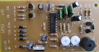
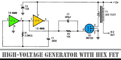
Circuit High Voltage Generator with HEX FET

The schematic diagram below show a circuit of high voltage generator. This circuit uses a 4049 hex inverter as an oscillator, and you can use ignition transformer from automotive engine. A fly-back transformer is possibly usable too. The 4049 will drive the IRF731 HEX FET. The Q1 must be heatsinked. Here is the schematic diagram of the circuit:

High-Voltage Generator with HEX FET

Continue[...]

Thursday, October 10, 2013

Amplifier Output Delay with Relay

This is a minimal circuit which I built to individual of my audio amplifier projects to control the presenter output relay. The end of this circuit is to control the relay which turns on the speaker output relay within the audio amplifier. The impression of the circuit is time lag around 5 seconds ofter the power up until the speakers are switched to the amplifier output to circumvent grating “pound” sound from the speakers. an added appear of this circuit is so as to is disconnects the orator just now once the power within the amplifier is finish inedible, so avoiding every now and then nasty sounds as soon as you trip the equipments inedible.

Amplifier Output Delay with Relay Circuit Diagram
Followed by power is functional to the power input of the circuit, the categorical stage of AC voltage charges C1. Then C2 starts to charge little by little through R1. while the voltage in C2 rises, the emitter output voltage of Q1 rises concurrently with voltage on C2. as the output voltage of Q2 is anticyclone an adequate amount of (typically around 16..20V) the relay goes to on state and the relay witches associate the speakers to the amplifier output. It takes typically around 5 seconds in the same way as power up until the relay starts to conduct (next to absolute epoch depends on the size of C2, relay voltage and circuit input voltage). as the power is switched rotten, C1 force not tied up it’s energy quite quickly. and C2 will transpire charged quite quickly through R2. into excluding than 0.5 seconds the speakers are disconnected from the amplifier output.

Continue[...]

Wednesday, October 9, 2013

Ebay has Surprising Bargains on Auto Sound Systems

Articles - Anyone that is familiar with Ebay knows that it is a literal one stop shop when it comes to hundreds of thousands of unique and common new and used items. It should then, come as no shock that Ebay is also a great place to find excellent bargains when it comes to auto sound systems. Yes, you heard that correctly. While you cant exactly test out your tunes over an Internet connection you can generally check out the exact same brands youll find at Ebay in your local automotive stereo and entertainment dealerships. The difference is that you can generally get your hands on the merchandise from Ebay at a fraction of the cost you would pay retail.


Many people often find better deals when going through Ebay than they would even be able to find at many retailers online. I am constantly amazed at the wonderful bargains that can be found on Ebay not only when it comes to auto sound systems but full entertainment packages for your vehicle. Not only can you find great bargains on sound systems for your vehicle you also can find some thrifty deals on amplifiers, subwoofers, speakers, speaker systems, and tools, tips, and tricks when it comes to installation.

While there is the fact that you cant hear the system for yourself if you purchase it on Ebay that can be easily overlooked by going to local retail stores in search of the same system. That should give you a very real indication of what the system you are considering on Ebay will sound like. You should look at local stores and online before making the bid on Ebay in order to compare prices and bid with confidence that you are in fact getting a bargain. Also be sure you pay attention to shipping and handling fees that might be involved in your package delivery. Ive found that with a select few Ebay retailers, they kill you on the handling expenses.

Another drawback with Ebay is the lack of customer service after the sale. Be sure to pay close attention to the ad details concerning customer satisfaction and recourse should something go wrong with your package. You should also be sure that you always purchase the insurance on your package should you win the bid. Even at discounted priced, auto sound systems are a pretty hefty investment and you should take care that you protect that investment.

The only serious drawback I have found to buying from Ebay when it comes to auto sound systems is the fact that you have to have your system installed. Installation simply doesnt come with these car stereos and not all installers are willing to do the installation if you didnt purchase the product from them. Installing an auto sound system isnt the simplest of tasks and you need to have a plan in place to get the system in your car before you commit to the purchase.

Whether you have serious plans to purchase an auto sound system in the near future or you are simply entertaining the notion, it is definitely worth checking out the wonderful options that Ebay has for your automotive listening pleasure. We live in a world where every penny seems to count, see how many you can save by shopping Ebay.s

Continue[...]

Tuesday, October 8, 2013

Basic Principles of the LC resonance circuit

If so far you are still confused how the actual origin of the resonance between the capacitor and the inductor is in progress, then the simple circuit above will answer your confusion.


Basic Principles of the LC resonance circuit

By understanding a simple electrical circuit above hopefully we will be able to understand the working principle of a series of more complicated and complex that uses the relationship as a series inductor and capacitors transmitter and receiver.

Note the picture above, when the switch SW1 is pressed and released back then obtained by the same signal as in the picture above signal. Initially when SW1 is connected to the voltage supply, the capacitor will make filling fast. Then when SW1 is released charge on the capacitor will be used by the inductor as the supply voltage. In accordance with the general nature of the inductor that the DC signal will be considered ordinary wire inductor such that current flowing quickly through the inductor and the charge on the capacitor decreases rapidly exhausted. Uniquely current that was flowing through the inductor and capacitor will fill the empty capacitor back through the other terminal (negative cycle). Charging kapasior place quickly, then inductor will burden the back so that emptying of cargo going back. That so happens repeatedly (resonance occurs between L and C) until the electrical charge had been used up by these two components in the form of power losses. Equations between regular wire inductor is the inductor with wire work as usual at the time of current flowing to him. Inductors But unlike ordinary wire when current flows to him and vice versa. So it will not happen short circuit if the inductor to get the supply voltage alternating current (AC). But in ordinary wire short circuit will still occur even if the voltage of alternating current.

From the above analysis we can conclude that the LC resonance occurs because one component part affected by the characteristics of other components. For frequencies generated depend on the value of L and C itself. The greater the value of both the frequency will be smaller and smaller the value of both the frequency value will be even greater.
Continue[...]

Monday, October 7, 2013

1W Audio Amplifier Using NCP2830

This 1w audio amplifier circuit is designed using NCP2830 audio IC manufactured by ON Semiconductor.This audio power amplifier ic designed for portable communication device applications and require few external electronic components.

1W Audio Amplifier Circuit using NCP2830 


NCP2830 is capable to provide 1W continuous output power in 8 ohms load.NCP2830 audio power amplifier main features are : high quality audio (THD+N = 0.04%) , low noise: SNR up to 100 dB, overall system efficiency optimization: up to 89% , Superior PSRR (−88 dB): Direct Connection to Battery , Very Low Quiescent Current 7 mA , Optimized PWM Output Stage: Filterless Capability , Selectable gain of 2 V/V or 4 V/V .
Continue[...]

Sunday, October 6, 2013

High Gain Crystal Earphone Amplifier

High Gain Crystal Earphone AmplifierHigh Gain Crystal Earphone Amplifier


This simple, one-transistor amplifier provides a voltage accretion over 1000 (60 dB) for active a aerial impedance bowl (crystal) earphone. The aerial accretion is accomplished by replacing the acceptable beneficiary resistor with an abnormal constant-current diode that food 1/2 mA yet exhibits a actual aerial attrition to the audio. This amplifier will accord accomplished array life, cartoon alone 500 uA.


Below is a archetypal appliance application it with the aboriginal clear radio ambit on this page. The amplifier provides acceptable aggregate with a bashful antenna. You may appetite a aggregate ascendancy as with the TL431 project! Or use the Crystal Radio RF Amplifier directly above for even more sensitivity with less than 2 mA current drain.


Continue[...]

Saturday, October 5, 2013

Fire alarm with light sensor

Fire alarm can be made with a light sensor (LDR) as in the article with the title of Fire Alarm with this LDR sensor. Principles of fire detection Fire Alarm with LDR sensor is to detect the presence of smoke through the LDR. LDR in the series Fire Alarm does not stand alone in detecting a fire, but the LDR in the pair with the light shining on the LDR.


Hence, in the detected smoke from the fire then the intensity of light received by the LDR LDR decreases and eventually trigger an alarm system on a series of Fire Alarm with this LDR sensor. Part 2 that in the series of Fire Alarm with Sensor LDR are some of the sensors, tone generator, audio power.


Image Series Fire Alarm with Sensor LDR


Function Section of the Fire Alarm with Sensor LDR
Part of LDR and light sensor facing to fire smoke detection
Part trigger using transistors and regulators as a trigger tone generator 7805
Tone generator section with IC UM66
Power audio section uses an audio power IC TDA 2002 which is equipped with voleme control (R3)
Continue[...]

Friday, October 4, 2013

Audio Surround Decoder Circuit

The circuit schematic drawings Surround Audio Decoder and its components and how to make it ,Audio surround decoder circuit. Surround sound quality is the process of adding the audio source by increasing the number of speakers. This is done by producing audio multitracking in a way that can be issued on a multichannel speaker.


Basically surround adopt an existing stereo system. The system uses a two-speaker stereo is right speaker and left speaker. With two speakers will be three-dimensional effect of the sound issued. With the surround, which generated three-dimensional effect was more extensive than in stereo. This is because the surround speakers that use more than two pieces. In addition to supporting the three-dimensional effects, stereo field theory is also noteworthy to organize the arrangement of sounds based on the type of sound produced.

Component List :

R1-2-7-8-12-13-18-19-20 : 47Kohm
R3-4-5-6-21-22-34-35    : 10Kohm
R9-10-11-14-15-16-17    : 15Kohm
R23-24-25-33-36         : 100ohm
R26-27-28-31-32         : 100Kohm
R29-30                  : 5.6Kohm
C1-8                    : 47uF/25V
C2-7-9-14-23            : 47nF
C3-6                    : 1uF/100V
C4-5-10                 : 33pF
C11-12-15               : 10uF/25V
C13                     : 82nF
C16                     : 18pF
C17                     : 100pF mini adjustable capacitor
C18                     : 2.2nF
C19                     : 4.7uF/25V
C20                     : 100nF
C21                     : 10nF
C22                     : 180pF
C24                     : 150nF
RV1-RV2                 : 2 X 10Kohm  Log. pot.
RV3-4                   : 10K Log pot.
D1                      : 1N4148
IC1-6                   : TL072
IC2-3                   : TL074
IC4                     : MN3101
IC5                     : MN3004


Surround effects can only be listened to speakers who have more than two channels. Surround is a technique commonly used in todays films that utilize multichannel speakers. Surround allows voice can move from side to side, is a moving side to side is to move from one speaker to another speaker. To create three-dimensional sound effects you can use a series of audio surround decoder.
Continue[...]

Thursday, October 3, 2013

300W subwoofer amplifier schematic

300W woofer subwoofer systemThis is an amplifier circuit that is formed from a transistor amplifier miraculous. This circuit is used in the speaker subwoofer with 300W maximum power on each side. To apply it, can be used in the room that is not too large, like the car. And the voltage needed between 25 to 42 Volt DC.

This is schematic of 300W subwoofer amplifier

subwoofer amplifier circuit rangkaian skematic
Continue[...]

Wednesday, October 2, 2013

Ultra Low Power LCD Indicator

This circuit serves as an ultra-low power replacement for multiple LED on-off indicators. It also has the advantage of being easy to read in full daylight. With the parts shown, it is possible to display four bits of information.


The display that I used has three digits and 2 decimal points for a total of 23 segments. Different groupings of segments can be used for the four indicators. I chose to use three squares (shown) and the three lower segments together (not shown) for the four indicators. Many other combinations could be used, one possibility would be to hard-wire numbers or letters out of each of the digits. Other LCD displays could also be used for different effects.

Circuit Diagram


A part that doesnt exist as far as I know, but should, is a single pixel LCD indicator (2 wire). An LCD manufacturer could probably make a lot of money with such a part. If such a thing exists, Id love to hear about it.

Specifications:
Operating Voltage: 3-15V (5V Nominal) DC
Operating Current: 250 microamps to 1 milliamp (400 microamps at 5V)
Operating Frequency: approximately 60 Hz

Theory:
The 7555 IC (CMOS 555 timer) generates a square wave clock signal at approximately 60 hz. This signal is sent to the LCD backplane and the inputs of the four CMOS 4070 XOR gates. If the other input (ind*) of an XOR gate is low, the gates output is a square wave that is in phase with the clock signal. If the ind* input is high, the gates output is out of phase with the clock.

Sending a signal to an LCD segment that is in phase with the backplane signal causes the display to stay blank. Sending an out of phase signal to the LCD segment causes an AC waveform to be applied to the segment which turns it black. Multiple segments are wired in parallel to generate the desired display patterns. The LCD segments require a tiny amount of current to operate, the CMOS gates also take very little power, hence the efficient nature of the circuit. It is necessary to tie the unused segments to the LCD backplane, otherwise they may partially turn on.

If more dislay bits are needed, additional XOR gates can be connected in the same manner. Up to 23 XOR gates could be used to drive the entire display, but a microprocessor and driver software would probably be easier to put together. By generating all of the signals with a microprocessor, all of the driving circuitry can be eliminated.

Other logic families could be used to make this circuit, it should work with a standard 555 timer chip and a 74LS86 XOR gate (different pinout), for example.

Some LCDs may not operate at very cold temperatures, an engineer at Lumex said that their components will work from -30C to +75C.

Construction:
The circuit was built on a standard prototyping plug board. All of the parts can be purchased for under ten dollars.

Use:
The four inputs of the CMOS 4070 IC can connect to outputs on a microprocessor, or any other logic output that needs monitoring. The supply voltage of this circuit should be the same as the driving logics supply voltage.

Parts:
1X Lumex LCD-S301C31TR 3 digit LCD display (from Digi-Key), or equivalent
1X CMOS 4070 quad XOR Gate, a CMOS 4030 should also work.
1X 7555 CMOS 555 timer chip
2X 100nF capacitor
1X 100uF 25V electrolytic capacitor
1X 10K 1/4W resistor
1X 100K 1/4W resistor

Continue[...]

Tuesday, October 1, 2013

10W Audio Amplifier with Bass boost

10W Audio Amplifier with Bass-boost
This Audio Amplifier design is based on the audio amplifier 18 watts, and was developed primarily to meet the requests of correspondents unable to locate the chip TLE2141C. It uses the NE5532 Dual IC wide, but obviously, its power output will be written in the 9.5 - 11.5W range, as the supply rails can not exceed ± 18V.

As amplifiers of this type are often used to drive small loudspeaker cabinets, the bass frequency range is rather sacrificed. Therefore, a Bass Boost control was inserted in the amplifier feedback loop, in order to overcome this problem, without loss of quality. The low elevation curve can reach a maximum of 16.4 dB @ 50Hz. In any case, even when the bass control is turned fully counterclockwise, the amplifiers frequency response curve shows a gentle rise: 0.8 dB at 400 Hz, 4.7 dB at 100 Hz and 6 dB at 50 Hz (referred to 1 kHz).
Continue[...]