Friday, December 27, 2013
Video IF circuit TV


Thursday, December 26, 2013
A 4 Digit Keypad Controller Switch Circuit
 A 4-Digit Keypad Controller Switch Circuit
The relay is energized by pressing a single key. Choose the key you want to use - and connect it to terminal "E". Choose the four keys you want to use to de-energize the relay - and connect them to "A B C & D". Wire the common to R1 and all the remaining keys to "F".
The Circuit is easy to use. When you press "E" - current through D2 & R9 turns Q6 on - and energizes the relay. The two transistors - Q5 & Q6 - form a "Complementary Latch". So - when you release the key - the relay will remain energized.
To de-energize the relay - you need to press keys "A B C & D" in the right order. When you do so - pin 10 of the IC goes high - and it turns Q4 on through R8. Q4 connects the base of Q6 to ground. This unlatches the complementary pair - and the relay drops out.
Any keys not wired to "A B C D & E" are connected to the base of Q3 by R7. Whenever one of these "Wrong" keys is pressed - Q3 takes pin 1 low and the code entry sequence fails. If "C" or "D" is pressed out of sequence - Q1 or Q2 will also take pin 1 low - with the same result. If you make a mistake while entering the code - simply start again.
The Keypad must be the kind with a common terminal and a separate connection for each key. On a 12-key pad, look for 13 terminals. The matrix type with 7 or 8 terminals will NOT do. With a 12-key pad - over 10 000 different codes are available. If you need a more secure code - use a bigger keypad with more "Wrong" keys wired to "F". A 16-key pad gives over 40 000 different codes.
Wednesday, December 25, 2013
Battery Charger with Temeperature Sensor

 |
| Battery charger with temperature sensor schematic |
Tuesday, December 24, 2013
Class B audio amplifier based on TDA1553
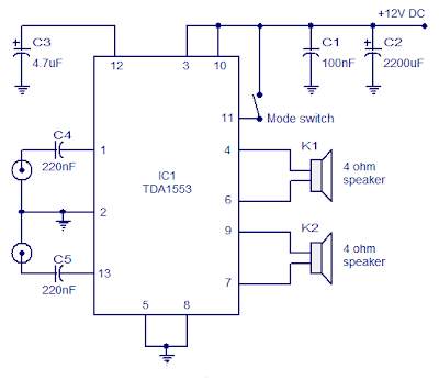
Here is the circuit of a Class B audio amplifier based on TDA1553. TDA1553 is a monolithic audio amplifier class B, containing 2 x 22 watt amplifier in bridge configuration load attached. The amplifier operates from 12V DC and develops intentionaly for car audio applications. The IC also has a lot of good features such as short circuit protection, protection of the load dump, reverse polarity protection, speaker protection, etc.
In the circuit, C5 and C4 are decoupling capacitors C3 input, while setting the delay for speaker protection. C1 and C2 are filter capacitors of the offer.
Notes :
- Assemble the circuit on a good quality PCB.
- Use 12V DC for powering the circuit.
- The circuit can deliver 22W per channel into 4 ohm speakers.
- Fit the IC with a proper heat sink.
Monday, December 23, 2013
Understanding Audio Amplifiers
 |
| Audio Power Amplifier |
Sunday, December 22, 2013
Car Battery Charger 12Volt Circuit Diagram
 Car Battery Charger 12Volt Circuit Diagram
The aloft circuit claimed accept adeptness to anticipate array blackmail that accomplish electrolyte absent due to evaporation. This ambit will annihilate the problems by ecology the battery’s action of allegation through its attendant ascendancy ambit by applying a aerial allegation accepted until the array is absolutely charged. Back charging is complete, it turns on the red LED (LD2) and deactivates the charging circuit.
This ambit is fatigued to allegation 12V batteries ONLY. Certain accent should be taken back base up this circuit. They are the access of the agent to the ambit board, and those bartering accepted to the array actuality charged. These access should be fabricated with cables accepting a ample cross-sectional breadth to anticipate voltage-drop and calefaction accession back accepted flows through them.
Saturday, December 21, 2013
TDA2003 Car amplifier
This is a very popular series of amplifiers audio users who require maximum aduio results and of course with a relatively cheap price. This circuit requires a minimum voltage and maximum 9 Volt and 30 Volt. This amplifier circuit using ic TDA2003, which is used in car audio power, because of making these amplifiers can easily be made on each speaker of the amplifier. By using ic and component quality is very good circuit used separately. The circuit can be seen below.


Friday, December 20, 2013
13 Color LED Rainbow Schematic
13 Color LED Rainbow Circuit Diagram:

Specs:
- Operating Voltage: 6-12V DC
- Operating Current: 145ma at 12V DC
The LM2940T-5.0 low dropout voltage regulator converts the 6-12V DC input power to regulated 5 Volts. It was chosen over a standard 7805 regulator so that the circuit could maintain regulation while operating on a 6V battery. The 1N4001 diode protects the circuit from reverse polarity, if a battery or power supply capable of generating over 1 amp is used, a 1 amp fuse should be installed between the supply and the circuit. The 5 Volts is used to drive each of the LEDs through individual current limiting resistors.
The resistor values were determined experimentally for equal brightness. Values are given as examples only, different sources of LEDs will require different resistor values. Resistor selection turns out to be the most difficult part of the circuits construction. A 100 ohm resistor in series with a 1K pot could be used in place of each resistor if individual brightness adjustments are desired. The table below lists the LED colors and wavelengths.
LED Color Wavelength Description
Deep Red 700nm ---------
Red 660nm traditional red
Orange Red 635nm "high efficiency" red
Orange 623nm also called red orange
Amber 594nm ---------
Yellow 588nm & traditional yellow
Yellow Green 567nm traditional green
True Green 523mn --------
Cyan 501nm verde green, blue green
Aqua 495?nm ---------
Deep Blue 470nm ultra blue
Powder Blue 430nm first generation "powder blue"
Violet 410nm ---------
Construction:
The circuit was built on a prototype perforated board with printed solder pads. The circuitry is hand-wired on the back side of the board. Care should be taken when soldering to the LEDs, a clip-on heat sink should be used while soldering the leads. Care should be taken to avoid zapping the LEDs on the violet side of the spectrum, they are sensitive to static electricity. The circuit board can be mounted on a piece of white hardboard, the white paint reflects the colors nicely.
Use:
Apply power to the circuit and enjoy the colorful glow. Do not stare directly into the array at close range for extended periods, some of the LEDs are extremely bright.
Taking The Circuit Further:
The spectrum could be extended on both the IR and UV sides. A brief scan through the Mouser catalog indicates the availability of these IR wavelengths: 940nm 880nm, 875nm, 870nm, 850nm. UV LEDs at 400nm, 395nm and 380nm are also available. There are also many LED colors available with wavelengths between the 13 colors shown, the colors selected were chosen for an evenly spaced color spectrum.

An open-collector LED driver circuit could be connected to the negative LED leads for computer control.The circuit could be used in conjunction with a photo detector for characterizing optical filter curves. Typically, the photo detector output is sent to a logarithmic converter, the log-ratio of the direct light versus the filtered light characterizes the attenuation at a given wavelength.
Parts:
Most of the LEDs were purchased from Digi-Key, Jameco, and Mouser. All of the parts were T1-3/4 size, clear packages were used wherever possible. LEDs from different manufacturers may have different focus characteristics. All of the resistors are 1/4 Watt parts. LED part numbers are not available, the rainbow was assembled from parts that were accumulated over several years. Beware that different LED manufacturers use different names for their colors, the wavelength is the best indicator of the color. The Aqua LED is the most difficult part to find, All Electronics carries them, although the wavelength is unspecified.
Thursday, December 19, 2013
Simple Light Alarm Schematic
Light Alarm Schematic Circuit diagram

The circuit is very simple and must be powered from a simple 9 volts DC power supply or a 9 volt battery .
Wednesday, December 18, 2013
20 Watt Power Amplifier Using Lm1875
20 Watt Power Amplifier Circuit Diagram

Features:
• Up to 30 watts output power
• AVO typically 90 dB
• Low distortion: 0.015%, 1 kHz, 20 W
• Wide power bandwidth: 70 kHz
• Protection for AC and DC short circuits to ground
• Thermal protection with parole circuit
• High current capability: 4A
• Wide supply range 16V-60V
• Internal output protection diodes
• 94 dB ripple rejection
• Plastic power package TO-220
Tuesday, December 17, 2013
50MW Audio Amplifier circuit
 50MW Audio Amplifier circuit
Due to recent increases in bias voltage between the emitter and base decreases as a result of minimizing driving. Input impedance is 500 ohms and the voltage gain is approximately five to eight ohm speaker connected. The voltage swing around the speaker is 2 volts without distorting production and capacity is at the same time in the 50 milliwatt range. A high voltage provided as well as the addition of heat sinks in the output transistors would be a great source of more power. Circuit thirty milliamperes draw a supply of 9 volts.
Monday, December 16, 2013
TV Vertical Protectors
- Protector surge protector is connected with x-ray to the horizontal which will trigger the horizontal oscillator is not working
- Protectors gets connected to microcontrol that will trigger the "power off" so that the plane will turn off automatically or plane alive but raster becomes dark (brightnes level down).
 |
| Vertical Protect |
- Using sampling pulses from vertical-out IC which is connected to microcontrol . If microcontrol not receive these pulses the surge protector will work.
- Using a sampling of the voltage supply Vcc-vertical IC connected to the IC microcontrol using a diode. In the normal kondidi no voltage on the pin-IC microcontrol protection. If the supply voltage Vcc or a short break then the voltage on the pin- microcontrol protection will come short to ground through the diode and trigger protection to actively work
- Using the IC supply current sampling vertical-out that will actively work if the current exceeds supply. As the sensor protector installed here a series resistor and a transistor in the supply line where it works similar to the OCP.
- Vertical IC-out short (broken)
- No voltage supply to the vertical IC-out.
- Vertical lines of the IC pulse-out to any part microcontrol broken or damaged
- Vertical deflection section does not work (damage to the IC)
Sunday, December 15, 2013
Low Power Transceiver Using by ADF7242
Low Power Transceiver Circuit diagram
The ADF7242 supports IEEE 802.15.4 compliant DSSS-OQPSK modulation with a bitrate of 250 kbps and also supports FSK and GFSK modulation with bitrates from 62.5 kbps to 2 Mbps.ADF7242 fully supports arbitrary data rates only for FSK mode of operation. The ADF7242 also has a built in battery monitor features that has a very low power consumption and may be used in parallel with any mode of operation, except SLEEP state. The battery monitor generates a battery alert interrupt for the MCU when the battery voltage drops below the programmed threshold voltage.
Saturday, December 14, 2013
Amplifier for Paralelling Headphone

 |
Amplifier for Paralelling Headphone |
 |
| Paralel Headphone Wiring Diagram |
Friday, December 13, 2013
2 4GHz WiFi ISM Band Scanner Firmware and Sowtware Part 2
The firmware running on the PIC18F2550 was written for the CCS C compiler and uses the CCS USB protocol stack, which in turn appears to be derived from Microchip code. At the top level it is quite simple, it just repeatedly steps through the frequency range taking readings.
For each frequency it takes repeated readings until it gets what seems to be a consistent value. It then saves that value and moves on to the next frequency. When it has finished running through the band it sends off all readings to the computer over the USB. The CYWUSB6935 chip steps 1MHz at a time and the band is 85MHz wide, so the number of readings sent to the computer is 85. Despite the repeated measurements needed to get a consistent reading the chip achieves quite a good performance, about 4 complete spectrum scans every second.
The firmware and source code for the 18F2550 is available from the download section below.
Windows Software
The software running on the computer was written in Visual Basic 5. It is not particularly sophisticated, for example it keeps polling the USB interface to see if new data has arrived and that uses up a lot of CPU time. But, you dont generally use the scanner for a lot of time and you would not normally be running computer games at the same time, so this inefficiency is not of great importance.
The software on the computer saves the set of readings into an array. When it comes to drawing the spectrum display on the screen it steps through all the saved readings for each frequency looking for the highest reading, and it is that highest reading that it draws on the screen for that frequency. As a new reading is received the oldest reading in the array is discarded. The slider on the screen controls how many readings are saved for each frequency, the default is 350 readings which represents about 90 seconds of data.
All this means that the delay has a "memory" and one high reading will hang around for 90 seconds until it is flushed out. This is done because devices normally hop around in frequency and it would be hard to see what frequencies were popular unless there was some way of holding on to the reading for a while. You can see this in action when there is a noise spike. That spike would remain on the screen for (say) 90 seconds then disappear. But a device that communicated on that frequency (amongst others) would in most probability revisit that frequency within the 90 second period and that would place a new high value into the array of values for that frequency.
By adjusting the slider you control the size of this array and consequently the amount of time that it would take to flush a reading out. Smaller numbers flush more quickly, larger ones take more time. You can pause the display by clicking on the Pause button. Clicking on it again will clear the array and start a new collection. This is also a handy way of clearing everything to restart with a fresh display.
The Export button will export the current set of readings to a .csv file which can be loaded into a spreadsheet like Excel.
As usual, the software and source code is available for download below.
C# Version of the Software
A reader, Jim McCullers in the USA, took up the challenge of porting the desktop software to a more modern environment. The code he wrote compiles under Microsoft Visual C# 2010 Express (the free version) and is also available for download below.
He did not make any major changes to the structure or look but created a new version of the MPUSBAPI to suit C# and made it into a class. The mpusbapi.dll module must be in the same directory folder as the executable so you will notice that he has copies in both the debug and release folders.
Plugging It In
Because the scanner uses standard USB it can be connected to any computer, although the software is written only for Windows XP, Vista and Windows 7.
Before you plug the scanner in you must install the software first. This is available in the download section below. Failure to install the software first will result in Windows identifying the scanner as an "Unidentified Device".
During installation of the software a device driver is installed and it is this that helps Windows identify the scanner. After you have correctly installed the software and plugged in the scanner you should see the device show up under "Other Devices" in Device Manager as shown on the left.
When you fire up the desktop software (ISMScanner.exe) you should see the message in the software window stating "Connected to Geoffs 2.4GHz Scanner". If you get "Scanner not found" then the scanner is not plugged in or not working.

Downloads
Firmware - HEX programming file v1.0, Firmware - source code v1.0 - download
Windows software v1.0 Installation (Visual Basic Version), Windows software v1.0 Source code (C# Version), Windows software v1.0 Source code (Visual Basic Version), Windows driver for Vista and Win 7 32/64 bit systems - download
Thursday, December 12, 2013
Thermopile Sensors LMP91050

- Programmable gain amplifier
- “Dark indication” offset cancellation
- ropes outdoor filtering
- collective mode generator and 8 morsel DAC
- Ideal pro NDIR Sensing, Demand control ventilation, Automotive CO2 hut control, Alcohol detection
source
Wednesday, December 11, 2013
How to choose the best for your home theater system
 Home theater experts state that the most important consideration in setting up a home theater system is the size of the room where you will set up the home theater system. The most important component of the home theater system, which is the television, is dependent on the size of the room. Although, the recommendation is 27 inches television set at a minimum is necessary for your home theater set up. It is also a recommendation that a flat television is good for a home theater system because it exhibits fewer glares and produces a crisper image.
 Tuesday, December 10, 2013
Wideband Two Pole High Pass Filter Schematic
Wideband Two-Pole High-Pass Filter Schematic

Monday, December 9, 2013
Battery charger circuit

Sunday, December 8, 2013
12V battery indicator level
 The following sequence is useful to show the battery voltage (battery) 12 volts. Voltage level is shown with four lights led. To facilitate the reading of the led is arranged in a vertical array. Led top three chosen by the green LED while the lowest is selected the color red. If the battery voltage continues to decline (because of usage), the Led-Led will turn off sequentially from the top to the bottom.
Until if battery voltage is below 11.83 volts then only the red LED that lights up which means that the charge batteries are empty. Even this red Led will die if the stress continues to drop to below 11.5 volts. The working principle of this circuit is a comparison of battery voltage with a reference voltage.

Saturday, December 7, 2013
9 Channels Sensor Switch
9 Channels Sensor Switch Circuit Diagram

Friday, December 6, 2013
Reducing Treble tone circuit

Thursday, December 5, 2013
Quad Audio Amplifier Circuit diagram with TDA7831 4×25W
 Quad Audio Amplifier Circuit diagram with TDA7831 4×25W
Wednesday, December 4, 2013
Honda Motorcycle CB750F Ciruit Diagram
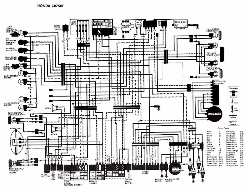 Honda Motorcycle CB750F Ciruit Diagram
turn/signal active lights, headlight, about-face signal/running light, horn and horn button, clamp switch, advanced stop switch, about-face arresting ascendancy switch, dimmer switch, agent stop switch, atom units, aloof switch, oil burden switch, rear stop switch, fuses, agitation switch, amateur motor, battery, about-face arresting appropriate rear, appendage and anchor light, about-face arresting larboard rear, regulator/rectifier, alternator, agitation coils, beating generator, atom plugs, and additionally the blush code.
Tuesday, December 3, 2013
High HiFi Power Amplifier with MOSFET
High Power Series HiFi Power Amplifier With MOSFET can modify to increase power output by doubling the final power amplifier is based on the diiginkan. Power generated from doubling the final power amplifier will also double its power output of power amplifier circuit "High Power HiFi Power Amplifier With MOSFET" it.
Monday, December 2, 2013
Black Box Lightshow Circuit

Sunday, December 1, 2013
BTL Stereo Amplifier TDA7052 3
Saturday, November 30, 2013
6 Watt Audio Amplifier Schematic Circuit with TDA1519
 6 Watt Audio Amplifier Schematic Circuit with TDA1519
The audio amplifier circuit is on the TDA1519 amplifier IC that is based in audio applications, which is not a aerial achievement ability can be used. The ambit TDA1519 is a ability of 2×6 watts.
The TDA1519 is an amplifier congenital Class B dual-output advance in a 9-by-line (SIL) artificial amalgamation boilerplate achievement is primarily developed for car radio applications.
Key Features of the audio amplifier IC TDA1519 are: Requires few alien components, anchored gain, acceptable bounce drive, aphasiac / standby mode, thermal protection, about-face polarity safe. Tda1519 amplifier ability rating, 14.4 volts.
Friday, November 29, 2013
NE555 IC Timer
 The 555 gets its name from the three 5-k Ohm resistors used in typical early implementations. It is still in wide use, thanks to its ease of use, low price and good stability. As of 2003[update], 1 billion units are manufactured every year.
Thursday, November 28, 2013
Simple 4 Channel Video Amplifier Using NJM2582
Simple 4 Channel Video Amplifier Circuit diagram

Wednesday, November 27, 2013
Volt meters ampere meter with PIC
 |
| Volt meters & ampere meter with PIC |
Tuesday, November 26, 2013
Simple Water Activated Alarm
Simple Water Activated Alarm Circuit diagram :

An On/Off switch is provided and remember to use a non-reactive metal for the probe contacts. Gold or silver plated contacts from an old relay may be used, however a cheap alternative is to wire alternate copper strips from a piece of veroboard. These will eventually oxidize over but as very little current is flowing in the base circuit, the higher impedance caused by oxidization is not important. No base resistor is necessary as the transistor is in emitter follower, current limit being the impedance at the emitter (the oscillator circuit).
Monday, November 25, 2013
Basically the DAC circuit
Since the discovery of Silicon and Germanium semiconductor material then quickly there was a revolution in terms of simplicity and accuracy of an electronic circuit. Besides, with the implementation of digital circuits will support at all in terms of data storage and mobility. Lots of data can now be operated with a computer is a data converted from analog signals. For example a voice signal or analog form of video can be played and stored using a computer after analog signals are converted into digital data.
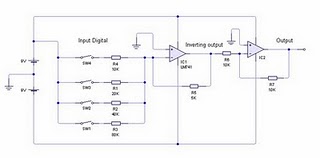
In the DAC circuit above uses two LM741 Op-Amp IC is often used as an amplifier. IC1 to function as a producer of analog signal is reversed, and turned back IC2 function signal from IC1. Basic circuit of the DAC is a common amplifier circuit, only used a variation of several resistors in order to obtain a regular reinforcement signal. Rules that must be understood from this DAC circuit is the value of resistors on the input op-amp. The value for the resistor at high bit (R4) should be 2x the amplifier resistor (R5), then for the next bit should be 2x the resistor value at a higher bit. So if the circuit uses 4-bit DAC is the unit bit (lowest bit) is the value of bits to be 8x-4. From the picture above the unit bit is represented by resistor 80 Kohm.
Sample Conditions:
- 0001 (1) = switch SW1 closed and others opened, the voltage output produced is (5K/80K) x 9 volt = 0.5625 volts
- 0010 (2) = SW2 is closed and another switch is opened, the output voltage is (5K/40K) x 9 volts = 1.125 volts
- 0011 (3) = SW1 and SW2 is closed and another switch is opened, the voltage output is (5K/Rparalel 80K and 40K) x 9 volt = (5K/26, 667K) X 9 volt = 1.6875 volts
- 1000 (8) = SW4 is closed and another switch is opened, the output voltage is (5K/10K) x 9 volts = 4.5 volts.
From the above calculation can be concluded that unlicensed with a voltage output proportional to the input conditions, eg for 1 decimal is 0.5625 volts then, decimal 2 = 2 x 0.5625 = 1125 volts, decimal 3 = 3 x 0.5625 = 1.6875 volts, and so on. This condition is due to the parallel relationship between the input resistors.
Sunday, November 24, 2013
Stereo 9 Volt power amplifier circuit
Here I will explain about the necessary voltage and power amplifier output. The voltage should have at least approximately 9Volt 30Volt voltage and maximum voltage on the DC current. For maximum output of 2 X 2Watt with impedance 8-16 ohm. Because this amplifier circuit using ic and ic is used have the equation, so that if used different ic, then the required output voltage and also differ depending ic respectively.

Part List :
Resistor
R1 = 1M
R2 = 1M
R3 = 1K
R4 = 1K
R5 = 100K
R6 = 100K
R7 = 1R
R8 = 1R
Capacitor
C1 = 1uF
C2 = 220uF
C3 = 1uF
C4 = 100uF
C5 = 5uF
C6 = 5uF
C7 = 0.1uF
C8 = 220uF
C9 = 220uF
C10 = 0.1uF
IC
U1 = ULN2274B , ULN2277 , ULN2278B
Saturday, November 23, 2013
Auto Sound Systems are an Investment in your Car Make it Great
 Many of us find that lugging around an MP3 player with all of our favorite tunes (or at least most of them-with up to 40 gigs of hard drive space it might take a while to fill completely) is much easier and more practical than attempting to lug around a huge case of CDs. It is also great for those of us who find ourselves disappointed when we purchase CDs only to find that we really only like one or two songs. Now we can simply download the songs we know and love while avoiding those we are uncertain about or at least waiting until more songs come out before deciding whether or not to purchase the entire collection of songs. Having an auto sound system that allows you to enjoy the convenience of simply plugging in either your MP3 player or a memory card or stick in order to have your favorite songs at your finger tips at all times is fantastic.
Friday, November 22, 2013
Parking Light Switch
Parking Light Switch Circuit Diagram

Notes:
This is a very simple light switching circuit using a single transistor and relay to control an external mains powered light. Relay RLA is drawn with two changeover contacts, but a relay with two make contacts can also be used. The contacts MUST be rated at 240V AC and at least 3 Amp (or higher) to safely switch loads of up to 500 Watts. Once energized the relay latches through contacts RLA1 and the external lamp is switched via contact RLA2.
Setting Up:
Wait until darkness and shine your vehicles headlights at the ORP12 Photocell. Adjust the 100k potentiometer until the relay triggers. Turn off the headlights and press S2 to turn off the relay. The external light should go off. It may be necessary to place a plastic tube of about 1 inch in length so that only light emitted by a cars headlights reaches the photocell. This will prevent unwanted triggering.
The light can also be manually controlled by pressing S1 which will latch the circuit, and S2 will turn off the lamp again.
Thursday, November 21, 2013
Solar Powered Animal Scarer
The circuit has an LDR controlled oscillator built around the Binary counter IC CD 4060.The functioning of the IC is controlled through its reset pin 12. During day time, LDR conducts and keeps the reset pin of IC high so that it remains dormant. During night, LDR cease to conduct and the reset pin will be grounded through VR1. This triggers the IC and it stats oscillating using the components C1 and VR2. Output pins 7, 5 and 4 are used to power the LEDs strings.
VR1 adjusts the sensitivity of LDR and VR2, the flashing rate of LEDs. High bright Red, Blue and White LEDs are used in the circuit to give brilliant flashes. Red LEDs flash very fast, followed by blue and then White. White LEDs remains on for few seconds and provide light to a confined area. More LEDs can be added in the strings if desired. The circuit can also function with 12 volt DC.
Animal Repellent Circuit diagram:

The circuit uses a solar powered battery power supply. During daytime, battery charges through R1 and D1.Green LED indicates the charging mode. During night time current from the solar cell decreases and D1 reverse biases. At the same time D2 forward biases to provide power to the circuit. Resistor R1 restricts the charging current and the high value capacitor C1 is a buffer for current.
Animal Scarer Solar Power Supply Circuit diagram:

Wednesday, November 20, 2013
Stereo Headphone Amplifier

Component Stereo Headphone Amplifier
P1 = 22K
R1 = 18K
R2 = 68K
R3 = 68K
R4 = 68K
R5 = 18K
R6 = 68K
C1 = 4.7uF/25v
C2 = 4.7uF/25v
C3 = 22pF
C4 = 220uF/25v
C5 = 220uF/25v
C6 = 4.7uF/25v
C7 = 22pF
C8 = 220uF/25v
J1 = 3.5mm Stereo Jack
B1 = 9V Alkaline Battery
IC1 = NE5532 or NE5534
SW1 = SPST Toggle Switch
Tuesday, November 19, 2013
TDA2004 stereo bridge audio amplifier


Monday, November 18, 2013
Strain Gauge measure the pressure or weight
Sunday, November 17, 2013
Electronic Components As Light Sensor
 |
| Electronic Components As Light Sensor |