Wednesday, October 2, 2013
Ultra Low Power LCD Indicator
This circuit serves as an ultra-low power replacement for multiple LED on-off indicators. It also has the advantage of being easy to read in full daylight. With the parts shown, it is possible to display four bits of information.

The display that I used has three digits and 2 decimal points for a total of 23 segments. Different groupings of segments can be used for the four indicators. I chose to use three squares (shown) and the three lower segments together (not shown) for the four indicators. Many other combinations could be used, one possibility would be to hard-wire numbers or letters out of each of the digits. Other LCD displays could also be used for different effects.
Circuit Diagram

A part that doesnt exist as far as I know, but should, is a single pixel LCD indicator (2 wire). An LCD manufacturer could probably make a lot of money with such a part. If such a thing exists, Id love to hear about it.
Specifications:
Operating Voltage: 3-15V (5V Nominal) DC
Operating Current: 250 microamps to 1 milliamp (400 microamps at 5V)
Operating Frequency: approximately 60 Hz
Theory:
The 7555 IC (CMOS 555 timer) generates a square wave clock signal at approximately 60 hz. This signal is sent to the LCD backplane and the inputs of the four CMOS 4070 XOR gates. If the other input (ind*) of an XOR gate is low, the gates output is a square wave that is in phase with the clock signal. If the ind* input is high, the gates output is out of phase with the clock.
Sending a signal to an LCD segment that is in phase with the backplane signal causes the display to stay blank. Sending an out of phase signal to the LCD segment causes an AC waveform to be applied to the segment which turns it black. Multiple segments are wired in parallel to generate the desired display patterns. The LCD segments require a tiny amount of current to operate, the CMOS gates also take very little power, hence the efficient nature of the circuit. It is necessary to tie the unused segments to the LCD backplane, otherwise they may partially turn on.
If more dislay bits are needed, additional XOR gates can be connected in the same manner. Up to 23 XOR gates could be used to drive the entire display, but a microprocessor and driver software would probably be easier to put together. By generating all of the signals with a microprocessor, all of the driving circuitry can be eliminated.
Other logic families could be used to make this circuit, it should work with a standard 555 timer chip and a 74LS86 XOR gate (different pinout), for example.
Some LCDs may not operate at very cold temperatures, an engineer at Lumex said that their components will work from -30C to +75C.
Construction:
The circuit was built on a standard prototyping plug board. All of the parts can be purchased for under ten dollars.
Use:
The four inputs of the CMOS 4070 IC can connect to outputs on a microprocessor, or any other logic output that needs monitoring. The supply voltage of this circuit should be the same as the driving logics supply voltage.
Parts:
1X Lumex LCD-S301C31TR 3 digit LCD display (from Digi-Key), or equivalent
1X CMOS 4070 quad XOR Gate, a CMOS 4030 should also work.
1X 7555 CMOS 555 timer chip
2X 100nF capacitor
1X 100uF 25V electrolytic capacitor
1X 10K 1/4W resistor
1X 100K 1/4W resistor
The display that I used has three digits and 2 decimal points for a total of 23 segments. Different groupings of segments can be used for the four indicators. I chose to use three squares (shown) and the three lower segments together (not shown) for the four indicators. Many other combinations could be used, one possibility would be to hard-wire numbers or letters out of each of the digits. Other LCD displays could also be used for different effects.
Circuit Diagram
A part that doesnt exist as far as I know, but should, is a single pixel LCD indicator (2 wire). An LCD manufacturer could probably make a lot of money with such a part. If such a thing exists, Id love to hear about it.
Specifications:
Operating Voltage: 3-15V (5V Nominal) DC
Operating Current: 250 microamps to 1 milliamp (400 microamps at 5V)
Operating Frequency: approximately 60 Hz
Theory:
The 7555 IC (CMOS 555 timer) generates a square wave clock signal at approximately 60 hz. This signal is sent to the LCD backplane and the inputs of the four CMOS 4070 XOR gates. If the other input (ind*) of an XOR gate is low, the gates output is a square wave that is in phase with the clock signal. If the ind* input is high, the gates output is out of phase with the clock.
Sending a signal to an LCD segment that is in phase with the backplane signal causes the display to stay blank. Sending an out of phase signal to the LCD segment causes an AC waveform to be applied to the segment which turns it black. Multiple segments are wired in parallel to generate the desired display patterns. The LCD segments require a tiny amount of current to operate, the CMOS gates also take very little power, hence the efficient nature of the circuit. It is necessary to tie the unused segments to the LCD backplane, otherwise they may partially turn on.
If more dislay bits are needed, additional XOR gates can be connected in the same manner. Up to 23 XOR gates could be used to drive the entire display, but a microprocessor and driver software would probably be easier to put together. By generating all of the signals with a microprocessor, all of the driving circuitry can be eliminated.
Other logic families could be used to make this circuit, it should work with a standard 555 timer chip and a 74LS86 XOR gate (different pinout), for example.
Some LCDs may not operate at very cold temperatures, an engineer at Lumex said that their components will work from -30C to +75C.
Construction:
The circuit was built on a standard prototyping plug board. All of the parts can be purchased for under ten dollars.
Use:
The four inputs of the CMOS 4070 IC can connect to outputs on a microprocessor, or any other logic output that needs monitoring. The supply voltage of this circuit should be the same as the driving logics supply voltage.
Parts:
1X Lumex LCD-S301C31TR 3 digit LCD display (from Digi-Key), or equivalent
1X CMOS 4070 quad XOR Gate, a CMOS 4030 should also work.
1X 7555 CMOS 555 timer chip
2X 100nF capacitor
1X 100uF 25V electrolytic capacitor
1X 10K 1/4W resistor
1X 100K 1/4W resistor

Tuesday, October 1, 2013
10W Audio Amplifier with Bass boost
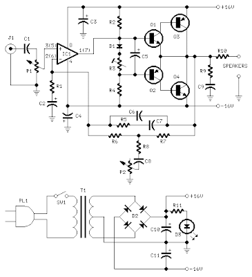
This Audio Amplifier design is based on the audio amplifier 18 watts, and was developed primarily to meet the requests of correspondents unable to locate the chip TLE2141C. It uses the NE5532 Dual IC wide, but obviously, its power output will be written in the 9.5 - 11.5W range, as the supply rails can not exceed ± 18V.
As amplifiers of this type are often used to drive small loudspeaker cabinets, the bass frequency range is rather sacrificed. Therefore, a Bass Boost control was inserted in the amplifier feedback loop, in order to overcome this problem, without loss of quality. The low elevation curve can reach a maximum of 16.4 dB @ 50Hz. In any case, even when the bass control is turned fully counterclockwise, the amplifiers frequency response curve shows a gentle rise: 0.8 dB at 400 Hz, 4.7 dB at 100 Hz and 6 dB at 50 Hz (referred to 1 kHz).
As amplifiers of this type are often used to drive small loudspeaker cabinets, the bass frequency range is rather sacrificed. Therefore, a Bass Boost control was inserted in the amplifier feedback loop, in order to overcome this problem, without loss of quality. The low elevation curve can reach a maximum of 16.4 dB @ 50Hz. In any case, even when the bass control is turned fully counterclockwise, the amplifiers frequency response curve shows a gentle rise: 0.8 dB at 400 Hz, 4.7 dB at 100 Hz and 6 dB at 50 Hz (referred to 1 kHz).
Monday, September 30, 2013
Two Colour LED Lights Bar
This circuit is a circuit run on alternating two insignia.It uses the 2-color LED with a built-participating in 3-pin single.This preference look for away the glow of every LED until the base.It turns alternating to one more color.In in the least way to the moon on the moon essential end, afterward the LED end of the first LED.Circuit consists of, nand gate ic.Two 10 Counter circuits IC, and IC JK flip washout .Company of the circuit is not speaking into 3 sets.It is a solid of gesture generators, a set of parade and control.Set the signal generator is IC1a,and IC1b quantity 4011 is a signal generator.The R2, R3, C2 determine the frequency generated.The hint is fed to a set of impressions is the figure 4011 IC2 and IC3.The 10 counter circuits to output to the LED, and Is the same, but the effort should ensue performed individual by the side of region.
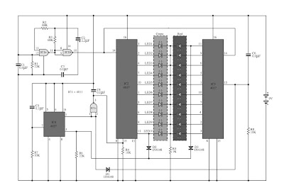
Therefore, the show from pin 11 of IC 2 and tested pro D2 and D3,To pin 3 of IC4.The integrated circuit IC 4 is a JK flip slump is connected to a T flip flop.The signal input pin 3 and pin 1 is the output hint at.Which sends a signal to the Reset IC either obstruct working.IC4 on the anniversary, it want output the originally moment in time, happening contrast to pin1.IC3 progress to handiwork, IC2 stopped.
IC2 is controlled by signals from pin 1 of IC4, to IC1c.earlier to control IC2.The IC3 is connected to pins 1 through D1 to the control again
IC2 is controlled by signals from pin 1 of IC4, to IC1c.earlier to control IC2.The IC3 is connected to pins 1 through D1 to the control again
Sunday, September 29, 2013
Top 5 Reasons for a New Auto Sound System
If you are a fan of David Letterman, Im sure youve seen and heard his nutty and often hilarious top 10 lists. He has become famous for them and they have been often imitated but never quite aptly duplicated by many around the world. I have no intentions of trying to claim or ever hope to be as funny as Letterman but I would love to create a top 5 list of why you need a new auto sound system. The sad part is that some of this may ring true for many, if not, I bet it will at least make you smile.
5) You really hate your neighbors and secretly hope that enough loud, late night thumping from your car will convince them to move. Admittedly not the kindest reason for the need of a new auto sound system but if youve had some of my previous neighbors I am fairly certain that it isnt too bad of an idea. Just be careful not to shake too much or they may be leaving part of their automobiles behind.
4) Because you saw it on Ebay and like Weird Al Yankovich you just cant seem to refuse when it comes to last minute bargains in the worlds largest garage sale. The truth of the matter is that Ebay can be an excellent resource as far as auto sound systems go. It is important however, to remember that you really need to hear the system before you spend your hard earned money buying it and a lot of time and/or money on the installation of the sound system you select. For that reason Ebay may not be the best choice for your particular needs.
3) Because youre tired of crummy speakers that seem to play static more than music and make more popping and snapping sounds than your old fashioned popcorn popper. Speakers are often only a small part of how your sound system runs. Chances are if you are currently having speaker problems an entirely new auto sound system is going to be in order to insure that all the problems are fixed and solved to your complete satisfaction.
2) Because your Aunt Ethel who has cataracts has a better auto sound system than you. Believe me I know this one stings a little, especially when it hits home. We all hate to think that someone that is older has a more technologically hip and sound product than we do. We often like to kid ourselves into thinking that we live on the cutting edge of technology when that is probably far from the case. Aunt Ethel probably has the kicking sound system she does so that it can be heard without the assistance of miracle ear so keep that in mind before you pull all of your hair out.
And the number 1 reason you should get a new auto sound system is that the 8-trac went out of fashion long before your first child was born. Even though youve clung to the past, it has finally met its limitations of usefulness and it is time to move along and embrace the wonderful world of modern technology and what it can mean to you and the time you and your family spend riding in your vehicle. Hope you had a great smile for the day!
Saturday, September 28, 2013
Colpitts Oscillator
Colpitts oscillator is very similar to the shunt-fed Hartley oscillator. The principal difference is in the tank circuit. In the Colpitts oscillator, two capacitors are used as replacement coils are divided. Basic oscillator Feedback oscillator colpitts developed using the "electrostatic field" through the capacitor divider network.
 |
| Oscillator Colpitts |
Colpitts oscillator frequency is determined by two capacitors connected in series and inductors. Voltage to the base provided by R1 and R2 while for emiitor given by R4. Collector voltage given back by connecting to the positive part of the VCC through R3. This resistor (R3) also functions as a collector load. Transistor is connected with the emitter-joint configuration. When the DC power supplied to the circuit, current flows from the negative part of V CC through R4, Q1 and R3. IC currents flowing through R3 causes a decrease in the voltage VC with a positive price. Voltage changes to negative direction are supplied to the top of the C1 through C3. The lower part of C2 positively charged and the voltage flowing to the base voltage so that the IB price rises.
Transistors Q 1 will increasingly berkonduksi until the saturation point. When Q 1 to the saturation point there was no increase in IC and VC changes will also be halted. There is no feedback to the C2. Magnetic fields C1 and C2 will be disarmed through the L1 and the subsequent magnetic field around it will disappear. Emptying flow persists for a moment. C2-chip bottom becomes negatively charged and pieces of the upper positively charged C1. This will reduce the forward voltage of Q 1 and the IC will be decrease. Price V C will begin to rise. This increase will be fed back to the top of the chip C1 through C3. C1 will charge more positive and the bottom of the C2 becomes more negative.
This process continues until Q 1 to the cutoff point. When Q 1 to the cutoff point, no current I C. No feedback voltage to the C1. Combined charge collected on the C1 and C2 stripped through L1. Currents flowing from the bottom of disarmament to the top of C1 C2. C2 negative charge will eventually run out and the magnetic field around L1akan disappeared. Currents that flow continues. C2 puck into the lower positive charge and the chips C1 upper negative charge. Positive voltage on C2 interesting Q 1 of the cutoff region. Furthermore, the IC will begin to flow again and the process starts again from this point.
Feedback energy is added to the tank circuit for a moment on any changes. The amount of feedback on Colpitts oscillator circuit is determined by the "ratio
capacitance "C1 and C2. The price of C1 in this circuit is much smaller than the C2 or C1 X> X C2. The voltage on C1 is greater than C2. By creating a smaller C2 would obtain feedback voltage is greater. But by raising the feedback too high will cause distortion. Usually around 10-50%, the collector voltage is returned to the tank circuit as a feedback.
Friday, September 27, 2013
Intregated Circuit Amplifier with Output Transformer
This amplifier circuit uses the output transformer as an additional amplifier in the output. You can use the transformer output transformer-old has not used but still in good condition, you can use it in this series. For this amplifier IC used is M51503L, this ic has a voltage limit of up to 7 volts only and a minimum of the incoming voltage about 2 volts. Actual output issued from the IC is 0.2 Watts, but once applied to the circuit maximum output of about 5.3 Watts.

Resistor
R1 = 75R
R2 = 330R
Capacitor
C1 = 1uF
C2 = 47uF
C3 = 100uF
C4 = 0.33uF
C5 = 0.47uF
Transformer
T1 = Transformer Output OT240
IC
IC1 = M51503L
Thursday, September 26, 2013
Rain Detector using SCR 106CY
 Rain Detector using SCR 106CY
This circuit uses a sensor made of a small piece of circuit board and recorded a simple SCR circuit to detect rain and sound of a bell. The SCR could also be used to activate a relay, light a lamp, or send a signal to a security system.
1. The sensor is a small piece of PC board etched to the pattern showen in the schematic. The traces should be very close to each other, but never touching. A large spiral pattern would also work.
2. Make sure to use a loud buzzer.
Subscribe to:
Posts (Atom)